Hi,
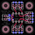
For my small headphone amp project I need an input/pass-through switch on the back panel (next to the RCA ins and outs) which will bypass the headamp if it is Off. For this I've designed a small PCB (3x3cm size) using two back-to-back Omron G6K relays to switch signals and their returns at the same time to eliminate the permanent ground loop if returns of two channels are connected together. Could someone comment if it makes sense to switch both signal and return in a single ended setup or I am overengineering here?
Regards,
Oleg
Attachments
Last edited:
Could someone comment if it makes sense to switch both signal and return
in a single ended setup or I am overengineering here?
Good idea, and no extra cost to do it. Ground loops are never a good thing.


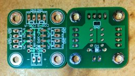
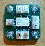
For my new preamp I needed a simpler version of the two-way selector. Attached is the result. The PCB accepts both through-hole and SMD Omron G6K-2x series relays and flyback diode. The populated board example uses through-hole parts.
Regards,
Oleg
Regards,
Oleg
Attachments
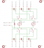
Just noticed that the schematic above is the wrong one. I don't know how it happened but attached is the correct one.
What is the value, and function of the capacitors between the relay pins?
Thanks,
David Baldock
Hi David,
The capacitors you mention are part of the RC low pass RF filter in combination with the output impedance of preceding stage. The value of those capacitors depend on the desired cutoff frequency and the output impedance of the stage driving particular input.
Regards,
Oleg
The capacitors you mention are part of the RC low pass RF filter in combination with the output impedance of preceding stage. The value of those capacitors depend on the desired cutoff frequency and the output impedance of the stage driving particular input.
Regards,
Oleg
Ah, so they're not part of the actual switching circuit?
I've been checking threads here on diyAudio, doing some research for an idea I have - to assemble two different types of input boards, for an integrated headphone amp / headphone switch.
One board type will be for line level inputs (Balanced = 2x 3-Pin XLR; Un-Balanced = 1x 1/4" or 2x RCA) going to the internal amp; and the other type for headphone level inputs (Balanced = 1x 4-Pin XLR; Un-Balanced = 1x 1/4") for signals from external amplifiers. Both boards will use 4x DPDT relays, one pair for the Balanced (L+), (L-), (R+), (R-) signals, and the other pair for the Un-Balanced (L+), (R+), (GND) signals. Depending on cost, the boards could be designed / populated as either single-sided or double-sided. The input connectors are probably what will determine the board size requirements.
I'm wanting it to be modular, so each small board (which can be mounted to the chassis rear panel) will contain the input connectors and relays for one input, and their outputs will be cabled to buses, either to the input of the internal amp, or to the board that connects to, and controls, the headphone jacks on the front panel of the chassis. In my parts bin, I know I've got a couple of manual, 6-position rotary switches - so up to that many, of each type of input board, could easily be used (depending on signal loading & noise).
For those of you in the USA, which board shops have you found to be the best cost & quality, for small production runs of audio circuit boards?
Thanks,
David Baldock
Last edited:
- Status
- Not open for further replies.
- Home
- Source & Line
- Analog Line Level
- Input/pass-through switch