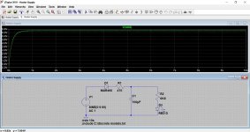
The cap eliminates the flicker. This shows the rectified supply voltage on top of the cap. This is all you need.
What is the purpose of D2 in this circuit? Also, at the bottom left, is that tied to ground?
What is the purpose of D2 in this circuit?...
The squiggle arrows are light coming out....
... at the bottom left, is that tied to ground?
No, it's just drawn that way.
SPICE demands that some point be called "0V ground" so it can do math relative to one point. In real life you don't need a ground to make power/light; witness a flashlight. In this case you sure don't want to ground one side of a heater winding; even guitar amps quit that in the 1950s due to the hum.
Mooly's latest sure will light the LED. I do wonder about bringing the heater AC onto the selector switch without significant filtering.
The 2-diode rectifier is often found but in this case makes 3.15V*1.414= 4.4V. Minus rectifier and LED drops leaves very little headroom for the current setting resistor. It's marginal.
The squiggle arrows are light coming out....
Gotcha... I thought it was a 2nd diode immediately before the LED. It IS the LED.
Mooly's latest sure will light the LED. I do wonder about bringing the heater AC onto the selector switch without significant filtering.
Do you think the 100uF cap is not sufficient? Would a full wave rectifier with cap be safer for avoiding AC hum on the signal-carrying switch? I'd rather over-engineer it then opt for the easiest option with fewest parts.
Which 2-diode rectifier are you referring to? The one that I posted from Rob Robinette's site?The 2-diode rectifier is often found but in this case makes 3.15V*1.414= 4.4V. Minus rectifier and LED drops leaves very little headroom for the current setting resistor. It's marginal.
Last edited:
Modern LEDs are linear down to very low current. (I remember when they weren't.)
Modern LEDs are brighter than ever.
Some modern LEDs are linear to low current and brighter than ever. You can still buy the GaP and GaAsP:N LEDs which are not bright. With the information Parts Express provides, you don't know which diodes you have.
In order to determine what current the LED should run at, you need a data sheet, which Parts Express does not provide. That's one of the many reasons I buy parts from actual distributors, such as Mouser, Digikey, Newark, et al.
At higher current, yes, I would favor taking heater AC. LEDs *will* run on AC, half the time. The reverse voltage is technically over the rating; I never killed one this way.
I never said to use them on AC. Specifically, I said to use a full-wave rectifier and smoothing cap to rectify the heater voltage and run the LEDs from the resulting ~8 V DC. That's honestly much safer than routing B+ through the chassis and wastes less power too. It also makes it possible to stay within the voltage limits of the switch OP is using. Routing hundreds of volt to a 42 V rated switch thinking that "it'll probably work" is not good engineering. What happens if something arcs over and kills the user? Funerals are expensive. As are lawsuits.
Just saying...
Tom
Specifically, I said to use a full-wave rectifier and smoothing cap to rectify the heater voltage and run the LEDs from the resulting ~8 V DC.
This is what I'm going to do.
You may not get much light at 0.5 mA with those. I'd go for 5 mA (which is what I based my recommendation on above).
Now if Parts Express would just give you an actual data sheet, we'd be able to figure out how much less light you'd get at 0.5 mA, but they don't...
How would I calculate this? What's the formula for luminous intensity? I'll add some LEDs to my next Mouser order so I know exactly what results to expect.
Also, how should I calculate the value for the voltage dropping resister? I seem to recall that it should be based on the transformer winding's peak voltage rather than the nominal 6.3V.
When it comes to trying to guess how much current you need for a particular LED then my advice would be to try it first.
You can calculate all you like but ultimately it has to look right. In your case it is only a single resistor that needs tweaking and so you could even rig a preset up and get the value spot on first. Always add a series 'safety' resistor though. Turn the preset to far and the LED will go dim... permanently 😀
If you want 'purer' DC then use a bigger cap. A 1000uF would cut the ripple down to millivolt level. Probably less than you would get running the LED from the HT line.
Attachments

Also, how should I calculate the value for the voltage dropping resister? I seem to recall that it should be based on the transformer winding's peak voltage rather than the nominal 6.3V.
The resistor has to drop the remaining voltage at the desired current so it becomes rather simple math:
LEDs have a rated forward voltage, usually 1.7-2.1 VDC depending on the color, intensity, mfr, etc. (Blue and White LEDs are much higher ~3.6-4.5VDC). If you have an 8VDC supply then the resistor must drop 5.9~6.3VDC at the DC current for which the LED is designed to operate. Example: 2.1V forward drop and 5mA, the resistor needs to be (8-2.1)= 5.9/.005 or ~1.2K.
..What's the formula for luminous intensity?
What luminous intensity do you want??
Mooly has said "try it", twice. You say you have LEDs. Can you score a 9V battery? 470, 1k, and 10K resistors? See how bright it is. Put it in your listening room to compare to ambient light and other LEDs on your gear.
Last edited:
What's the formula for luminous intensity
If you are asking for LI vs current, I don't know that one exists. Intensity is one of the parameters baked into the device. Changing the current through the device actually changes the intensity very little. LEDs are current mode devices. You should operate the device at the current specified in the data sheet. The correct way to dim an LED (electronically) is with PWM; square waves with a variable duty cycle at the voltage/current as determined by the dropping resistor and the data sheet.
If all else fails, use smoked acrylic on the faceplate; it comes in a variety of neutral density "colors" and can effectively tone down bright LEDs.
Yes it is possible to alter the intensity with current, but the adjustment range is quite small: 5:1 brightness from 2.5mA to 12.5mA vs 100:1 using PWM at a fixed current level. If 20% brightness is acceptable, then you are good to go.
I couldn't imagine running an LED rated for 10mA at 70mA, the MTBF would drop like a rock.
Running the LED at low current has problems as well. While the LI vs current curve may be linear, the I/V curve is not. Operating an LED rated for 10mA at <1mA could put it at a critical part of the curve; even slight variations in voltage could cause it to extinguish completely or become much brighter than intended. If the OP is looking to do this, I would consider adding a voltage regulator to the DC supply; if the application will see large temp changes, I would include temp compensation as well.
Also, how should I calculate the value for the voltage dropping resister? I seem to recall that it should be based on the transformer winding's peak voltage rather than the nominal 6.3V.
Assuming the transformer outputs a sine wave, the peak value is the RMS value multiplied by sqrt(2). Note that you lose some voltage across the rectifier bridge as well, so the math becomes slightly more involved:
VDC = (VRMS-2*VD)*sqrt(2)
VRMS = 6.3 V in your case
VD is typically 0.6-0.7 V for a silicon diode, though it varies with current, temperature, and diode composition.
So figure: VDC = (6.3-2*0.7)*sqrt(2) = 6.92 V
A bit lower than the 8 V I was guessing. Above assumes a conduction angle of 0º, i.e. the diodes conduct for an incredibly small amount of time. That's probably not the case, so the actual voltage may be a tad lower still. If you want to know the exact value, I suggest running a simulation of the circuit or building it and measuring the voltage.
Once you've established VDC, the LED series resistor can be calculated as:
R = (VDC-Vf)/I
Where Vf is the forward drop across the LED (see its data sheet) and I is the desired current.
... or as others have said, try with a 9 V battery and a resistor. Just keep the current reasonable (20 mA, max).
Tom
Last edited:
Data for Mouser's 10-cent plain LEDs sure shows a slope.
It sure does. However the perceived brightness does not change that much as function of luminous intensity. You can look up Weber's Law if you're interested. I forget if it's a 4x or 10x difference in luminous intensity that's needed for light to be perceived as twice as bright.
Tom
The current to light conversion constant does exist, and it is quite linear for all modern LEDs, including the cheapest ones; it is "baked in" by the manufacturing process, but it remains consistent from µA's or even less, up to the destructive level.If you are asking for LI vs current, I don't know that one exists. Intensity is one of the parameters baked into the device.
.Changing the current through the device actually changes the intensity very little. LEDs are current mode devices
Changing the current changes the intensity (as measured by an optical power meter) in an almost perfect proportional manner.
The perceived intensity is an entirely different matter: our senses operate on a logarithmic scale, and in order to double the perceived brightness, you need to decuple the optical power (thus the current)
You can operate a LED at whatever current suitable, provided it is below the abs max ratings.You should operate the device at the current specified in the data sheet.
It is one of the possible way, certainly not the only correct oneThe correct way to dim an LED (electronically) is with PWM; square waves with a variable duty cycle at the voltage/current as determined by the dropping resistor and the data sheet.
I've dimmed LEDs by current starving them. Worked great and allowed me to have the LEDs be dimly on when the equipment was on and brightly on for the selected input. Tres cool.
The only type of LED I was not able to dim (much) by current starving, was a white LED. I tried a couple different ones. Same depressing result. I guess you have to resort to PWM to dim those.
Tom
The only type of LED I was not able to dim (much) by current starving, was a white LED. I tried a couple different ones. Same depressing result. I guess you have to resort to PWM to dim those.
Tom
Last edited:
...the adjustment range is quite small...
I couldn't imagine running an LED rated for 10mA at 70mA...
...the LI vs current curve may be linear, the I/V curve is not. ...could put it at a critical part of the curve; even slight variations in voltage could...
I don't know where this all comes from. Measurements? Tests? Experience?
I've run LEDs over >200:1 range of brightness in control systems where nonlinearity would suck. Sometimes just variable voltage through a resistor, sometimes a "current source".
I've run "20mA" LEDs in multiplexed displays with >50mA but 1/8th of the time. The efficiency does fall-off, but not much.
I've run 100mA in a 20mA LED for hours. The color changes. I am sure life would be quite short. But they don't blow-up quick.
The V/I curve doesn't come into the picture if you run more than a few Volts through a resistor. Over a very wide range the LED obeys the standard diode log V/I curve, no "critical part" monkey-business. At high current a parasitic series resistance makes V rise faster than log. And back in the 1970s I found about 10% of economy LEDs acted like they had ~~2K of shunt resistance, so the *did* go "off" near 1mA. Then as now, you try another LED. (Even when I built 10x8 LED arrays and replacement was annoying.)
I am quite sure that >9 of 10 LEDs sold today will light bright enough to indicate well with under 1mA actual current. While we typically get current from some voltage, if the voltage is more than a few V then a simple resistor will set the current as desired.
I don't know where this all comes from. Measurements? Tests? Experience?
All of the above.
I've run LEDs over >200:1 range of brightness in control systems where nonlinearity would suck. Sometimes just variable voltage through a resistor, sometimes a "current source".
I just tested this using a variable bench supply. To achieve a perceived doubling in brightness, I had to change the voltage from 5V to 12V; to achieve another doubling, voltage went from 12V to 30V. On the low side, halving the brightness dropped the voltage from 5V to 2V. As I approached the Vf of the LED (1.7V), the change in voltage became increasingly smaller; at bottom, a change of 10mV changed from dim to off.
As I stated previously, you can change the brightness via voltage/current. As the relationship with V is not linear, the practical range of brightness is fairly limited on the top side, and somewhat critical on the low side.
I've run "20mA" LEDs in multiplexed displays with >50mA but 1/8th of the time. The efficiency does fall-off, but not much.
So the RMS current level was ~6mA? Is this not PWM as I suggested?
I've run 100mA in a 20mA LED for hours. The color changes. I am sure life would be quite short. But they don't blow-up quick.
Why would anyone want to do this? Do you typically operate semiconductor devices at 400% over mfr's ratings?
The V/I curve doesn't come into the picture if you run more than a few Volts through a resistor. Over a very wide range the LED obeys the standard diode log V/I curve, no "critical part" monkey-business. At high current a parasitic series resistance makes V rise faster than log. And back in the 1970s I found about 10% of economy LEDs acted like they had ~~2K of shunt resistance, so the *did* go "off" near 1mA. Then as now, you try another LED. (Even when I built 10x8 LED arrays and replacement was annoying.)
I'm not sure I get your point, or are you just trying to be pedantic? This part would seem to confirm my bench tests as posted above.
I am quite sure that >9 of 10 LEDs sold today will light bright enough to indicate well with under 1mA actual current. While we typically get current from some voltage, if the voltage is more than a few V then a simple resistor will set the current as desired.
Changing the current via a resistor will certainly be more practical than changing the voltage. As Kevinkr suggested, the OP should experiment with different values.
voltage regulator
That's what I was thinking. For the price of a 7805 and a couple of caps he could have a well defined voltage to work with. For that matter he could use a current source, which could be as complex as a LM317 or as simple as a single transistor.
For that matter he could use a current source, which could be as complex as a LM317 or as simple as a single transistor.
A current source with an LM317 and a resistor is actually a quite elegant solution. I did that in an solid state audio amp. Bolted the LM317 to the heat sink to get rid of the heat. That made it super easy and more reliable than a power resistor.
Tom
- Status
- Not open for further replies.
- Home
- Source & Line
- Analog Line Level
- Input/Output Indicator LED Lights