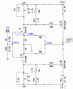
Hi everyone, I have a question about the F5 input scheme.
If it is supposed to accept consumer grade 2Vrms input, the the input jfet gates are going to be forward biased as soon as the input level exceed +- 0.7V.
If so, then the resistor in series with the gate does become the only impedance, that is 4.7k ohm. Is'nt that too much of a load for a preamp?

If it is supposed to accept consumer grade 2Vrms input, the the input jfet gates are going to be forward biased as soon as the input level exceed +- 0.7V.
If so, then the resistor in series with the gate does become the only impedance, that is 4.7k ohm. Is'nt that too much of a load for a preamp?
the the input jfet gates are going to be forward biased as soon as the input level exceed +- 0.7V.
The input fet sources are not grounded, so the amp can accept more than 0.7V peak due to
the action of the feedback network. Similar action happens in many amps using nfb.
not really
with 2Vpp input , 2Sj74 is seeing aroundish 70mVpp of G-S drive amplitude
2SK170 even less
edit ....... with 2Vrms , that amplitude is ~100mVpp
with 2Vpp input , 2Sj74 is seeing aroundish 70mVpp of G-S drive amplitude
2SK170 even less
edit ....... with 2Vrms , that amplitude is ~100mVpp
> gates are going to be forward biased
{as Rayma says...} this is a high negative feedback affair. A fraction of the output is subtracted from the input.
The forward gain is about 200. The NFB network is 1/6.
(Neglecting the 4.7K:47K input divider) A 1V input makes 6V output. For this to happen, the input stage needs only 6V/200 or 0.03V signal.
Keep the 50:10 NFB network but replace the forward amplifier with a chip op-amp, with forward open-loop gain of 100,000 (for low audio frequency). For 6V output, you will have 0.000,06V between the two input pins. While this is hard to directly measure (it pushes the limits of benchtop instrumentation), you can confirm that with very-high gain the input difference "vanishes" and for just high gain the input difference is very small. Go to the other limit of useful NFB, a tube guitar amp, and you may find that 3V input makes 1V of NFB signal and still 2V across the G-K junction.
Only a NO-NFB connection takes full jack signal across its first junction.
Attachments
- Status
- Not open for further replies.
