Hi
Please help me with this circuit:
It is input in guitar combo Kustom 16.
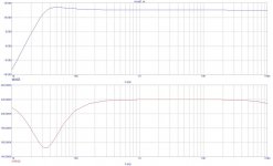
The simulation shows that it slightly boosts the frequency 50Hz (~1db).
At first I thought that in this circuit is a kind of bootstrap for more high input impedance but why dumping resistor 220k at the input?
Why boost 50Hz?
Thank you in advance for the answers.
😕
Please help me with this circuit:
It is input in guitar combo Kustom 16.
The simulation shows that it slightly boosts the frequency 50Hz (~1db).
At first I thought that in this circuit is a kind of bootstrap for more high input impedance but why dumping resistor 220k at the input?
Why boost 50Hz?
Thank you in advance for the answers.
😕
Attachments
No, it's correct. It's basically a 2nd order Sallen-Key high-pass filter - but with gain. It's a valid circuit - used very often by Fender - but the approximation of gain and response is no longer as straightforward as in the basic Sallen-Key design. ...Nothing a SPICE sim couldn't crack in an eyblink, though.
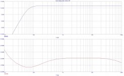
For reference, basic Sallen-Key filter:
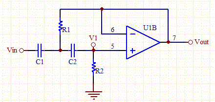
That kind of "hump" is characteristic for the response. It's effect of ~ 1dB boost is quite negligible compared to - 50 dB cut in low frequencies the filter also seems to be introducing.
For reference, basic Sallen-Key filter:
That kind of "hump" is characteristic for the response. It's effect of ~ 1dB boost is quite negligible compared to - 50 dB cut in low frequencies the filter also seems to be introducing.
Last edited:
I have no idea why this circuit was used as the e-guitar combo input stage...
The circuit is incorrectly drawn, i.e it is in error, regardless of how the error ocurred.
It does not conform to a conventional Sallen-Key prototype, in all probability it is a conflation of 2 designs, one of which was single rail and used R1-R3 to set the operating point. Otherwise the gain-setting loop to the inverting input should not be connected to the filter loop which connects to the non-inverting input. You might be able to simulate it but how would you design it?
w
Thanks Folks!
Do you think that small redesign will improve the performance? (noise, low cut, etc.?)
What would you propose for do with this (best for the guitar)?
Do you think that small redesign will improve the performance? (noise, low cut, etc.?)
What would you propose for do with this (best for the guitar)?
Thanks Folks!
Do you think that small redesign will improve the performance? (noise, low cut, etc.?)
What would you propose for do with this (best for the guitar)?
It depends what do you (amp owner) want. Tell us what type of sound, tone, you like. We will (or not 😀) tell you how to create it. There is no such a ting as:ultimate, one and only solid state guitar pre.
In terms of noise - is it to noisy amp ? If not - why even bother? 🙂 If yes - problem may be hard to crack, since passive guitar pickups have lot of resistance. Every resistance is a source of noise. Best way to avoid it it would be using amplifier with low current noise.
But, I suspect - noise should not be a problem if your guitar amp is not hi-gain beast.
Is it clean or distorted amp ? If it's distorted - hi-pass filter is needed to avoid muddy, buzzy sound. That 1dB bump its not a problem. Characteristic of a guitar amp is not (and it should not be) flat.
Go to best guitar amp site and read, read, read:
Guitar Preamp
It's about tubes, but... The way of making freq. characteristic is the same in solid state.
Remember - most important in guitar amps is its feel, sound, tone, number of neighbours angry when you finish playing and number of devils you created. hahahha 😀
Not one decibel this or other way. To make decent tone sometimes you have to add or remove 10 dB somewhere 🙂.
Last edited:
Hi
I knew it before
My Kustom Arrow 16 became silent after decoupling power supplies on opamps into one star gnd point.
Of course
there is nothing more to do
but further experimenting...
thanks and
The circuit is incorrectly drawn, i.e it is in error, regardless of how the error ocurred.
No, it's correct. At one time Fender used it as an input stage in about every SS amp they produced, such as, for example, this one:
http://www.fender.com/support/amp_schematics/pdfs/Deluxe_90_Schematic_-_11x17.pdf
It does not conform to a conventional Sallen-Key prototype, in all probability it is a conflation of 2 designs ..
What I said already. The only drawback from that is that the filter's function and type depends on gain and you can't estimate the outcome with any reasonably simple equation. Nowadays we have SPICE so it doesn't matter.
Otherwise the gain-setting loop to the inverting input should not be connected to the filter loop which connects to the non-inverting input.
Why not? Many OpAmp filter designs exploit that idea.
So - since normally tuned E string is 82 Hz we can say that this is almost completely flat freq response🙂.
best regards
best regards
No, it's correct.
Look at the simulation. I don't care how many times they've used it, that just proves how easy it is to copy an error. Particularly nowadays...
Nowadays we have SPICE so it doesn't matter.
Oh. Maybe Fender haven't got spice?
w
Looking at the simulation, maybe it's intended to keep people from plugging in bass guitars?
w
Hell of a way to run a railroad...
w
Hell of a way to run a railroad...
Last edited:
OK
there are many ideas about the input impedance,
what is better:
there are many ideas about the input impedance,
what is better:
- high inp impedance >=1M
- or ~220k to damp cable's variable capacitance?
high inp impedance >=1M, if you would like to get a voice from your pickup
http://www.blueguitar.org/new/misc/gtr_lemme.pdf
http://www.blueguitar.org/new/misc/gtr_lemme.pdf
All the stuff in guitars works at ~250k.
It's conventional to have an impedance at the receiving end of the cable that matches that at the sending end. The connection between the guitar and the amplifier is not a 'transmission line' in the radio sense, it's too broadband and it's 'electrically short' but the most efficient transfer of power still takes place when the sending and receiving resistances are the same. This is why the 220k resistor is clagged across the input of your circuit.
w
In terms of noise - is it to noisy amp ?
What I think
is important to every guitar input preamp:
- the first stage should have right input impedance,
- right frequency response
- and good amplification/noise factor ratio
- no matter distortion until it allows clean sound.
- Status
- Not open for further replies.
- Home
- Live Sound
- Instruments and Amps
- input in guitar combo