Hi
Wondered if someone here would be interested in explaining some basic about input buffers. I have tried to search a bit and checked wikipedia, but it seems like I'm mostly just find computer stuff.
What I'm wondering about is:
- What is the purpose of the input buffer? Must you have one?
- I have seen, in relation to hypex amp, that they mention input buffer as a way for oem's to add "house color" to the amp. What kind of design is there and how can you know what sound a given design will result in?
How can you get a sound with as little color as possible?
- Is there any examples of input buffer circits out there? I would love to see schematis for a buffer and then pictures of the actual input buffer itself.
- Is there input buffers that can be bought?
You know, just all that general expert knowledge that I would love to know but does not have the skills to know...
Any help and input is appreciated. Thanks in advance!
Input buffer is usually a unity gain stage that provides an increase in current but not voltage.
Many people like tube buffers (or low-gain preamps) in front of their class D amps, it makes them sound more natural and smoother in the high end, and the extra drive gives the sound more impact. I'm not sure you would count tubes as colored or not, but it certainly doesn't have to be. An example is Broskie's cathode follower circuit, although there are many others. Ofcourse there are solid state buffer circuits as well.
Many people like tube buffers (or low-gain preamps) in front of their class D amps, it makes them sound more natural and smoother in the high end, and the extra drive gives the sound more impact. I'm not sure you would count tubes as colored or not, but it certainly doesn't have to be. An example is Broskie's cathode follower circuit, although there are many others. Ofcourse there are solid state buffer circuits as well.
Cool, I'm looking into either running some ice 200asc's straight, or adding a buffer also. Is it to increase input impedance also? So it's an easier load on the preamp?
A buffer changes the impedance of the circuit.
It can change a relatively high impedance to a low impedance.
It can change a relatively high impedance to a low impedance.
Thanks for the input!
I'm looking into building a input buffer for a nc500 that I have got my hands on.
I have done some buildings before, a tube-preamp, some subs and some speakers with crossover ++.
But I have never build a pcb layout. That means that I have some challenges with basic understanding of the schematics, knowing basic stuff that I might be expected to know as well as some practical stuff about the process.
The idea is to build based on this circuit that Bruno suggest. As far as I know I can not just buy this, so I will have to build it. I might build it anyway, but if it is possible to by the input buffer I would like to know that as well, so please tell me.
This is the circuit that Bruno suggest in the datasheet for the nc500, page 11:

As far as I understand the AK4396 is an example of a DAC and is not a part of the circuit. I will have XLR input's for my amps.
I have marked what I believe will have to be part of the circuit inside the read square in the figure below.
Does this look like I'm on the right track?
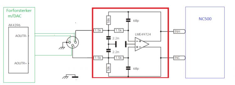
If so then the next step will be to find a utility to draw the circiut and the pcb layout.
I have downloaded EAGLE freeware software. Currently I'm unable to locate the LME49724 in any of the libraries so I'm a bit stuck due to that.
I'm also wondering if the circuit is complete or if the actual physical circuit should contain something more that is just left out because the circuit Bruno has drawn up might be more of a principal drawing than a production circuit.
Sorry, lot of questions spinning around as I have a LOT to learn here 🙂
I'm looking into building a input buffer for a nc500 that I have got my hands on.
I have done some buildings before, a tube-preamp, some subs and some speakers with crossover ++.
But I have never build a pcb layout. That means that I have some challenges with basic understanding of the schematics, knowing basic stuff that I might be expected to know as well as some practical stuff about the process.
The idea is to build based on this circuit that Bruno suggest. As far as I know I can not just buy this, so I will have to build it. I might build it anyway, but if it is possible to by the input buffer I would like to know that as well, so please tell me.
This is the circuit that Bruno suggest in the datasheet for the nc500, page 11:
As far as I understand the AK4396 is an example of a DAC and is not a part of the circuit. I will have XLR input's for my amps.
I have marked what I believe will have to be part of the circuit inside the read square in the figure below.
Does this look like I'm on the right track?
If so then the next step will be to find a utility to draw the circiut and the pcb layout.
I have downloaded EAGLE freeware software. Currently I'm unable to locate the LME49724 in any of the libraries so I'm a bit stuck due to that.
I'm also wondering if the circuit is complete or if the actual physical circuit should contain something more that is just left out because the circuit Bruno has drawn up might be more of a principal drawing than a production circuit.
Sorry, lot of questions spinning around as I have a LOT to learn here 🙂
A very good working design can be found in the designer's manual of the icepower 50asx module. https://www.google.de/url?sa=t&source=web&rct=j&url=http://www.icepower.dk/files/solutions/icepower50asx2_designersmanual_1-1b_03072012.pdf&ved=0CBsQFjAAahUKEwjgwuSf4YDJAhXlg3IKHY_DDjk&usg=AFQjCNEsBcLLRCUFeoF7-Co3TQ7W9PXgXw&sig2=KkIb4u44CRhI75sXqCXeQQ
Hi TEK,
If you are looking for design and PCB look at Nisbeth web site :
https://theslowdiyer.wordpress.com/?s=buffer
I've build Buffer for 50ASX2 with his PCB design, VERY good sounding 🙂
See post #56 ont thread ICEpower 50asx2 modules.
http://www.diyaudio.com/forums/class-d/190311-icepower-50asx2-modules-6.html#post4425894
One thing you must know is if you need balanced or unbalanced input on your buffer.
If the output of the buffer is connected to the input of the Ncore, then you need a balanced output.
Last edited:
- Status
- Not open for further replies.
- Home
- Amplifiers
- Class D
- Input buffer for class D amps