I was thinking that the walls would be in the neighborhood of 10-14 mm thick (and more, at some junctures). The curved inner surfaces are supposed to guide the air pressure where it will do some good instead of flexing, but perhaps some additional structural buffering is needed.
Do you have any links to images of speaker enclosures that use the honeycomb approach?
Jeff
There is no need for the inner surfaces to "guide airflow". There is no appreciable "flow" happening internally.
Nobody makes them that way AFAIK but you will often see "ribs" added to molded parts to stiffen the structure. Think of the honeycomb (one side of the "comb' is open to the inside) as lots of interconnected ribs and you get the idea.
Do you have any experience with injection molding and plastics?
That is not a horn, even if it is horn shaped. It may amplify/filter a small range (a horn is good for 3-4 octaves) but is likely to damp everything else down.
I don't have enough acoustic engineering background to know why something that is shaped like a horn is not a horn.
Also, I was really only expecting 1 octave of assistance, improving the output over that of a 4" driver in a sealed box over the range of 100-120 Hz down to, say, 50-60 Hz.
Is this realistic? It's not like I want to thump the floor with it (it's only going to have 5-10 watts peak for a portable speaker).
If not, can you point me to an information source so I could improve on this?
Jeff
There is no need for the inner surfaces to "guide airflow". There is no appreciable "flow" happening internally.
Nobody makes them that way AFAIK but you will often see "ribs" added to molded parts to stiffen the structure. Think of the honeycomb (one side of the "comb' is open to the inside) as lots of interconnected ribs and you get the idea.
Do you have any experience with injection molding and plastics?
Yeah, 'flow' is not the right term for this, but there is an overall 'direction' involved (around the baffles and out the port).
So these ribs on the interior surfaces do not have a negative effect on the propagation of the sound waves through the enclosure? I would think that they would be creating 'eddys' (again, not the correct term, but you probably understand what I am getting at).
My experience with injection molding is limited to much simpler structures (card ejectors, etc.). I'm going into new territory here.
Jeff
improving the output over that of a 4" driver in a sealed box over the range of 100-120 Hz down to, say, 50-60 Hz.
For a horn to be a true horn, its mouth circumference should be approximately the wavelength of the lowest note of interest. 1 wavelength at 60 Hz almost equals 19 ft.
dave
The internal behavior of the air is more like "compression and rarefraction" than "flow". Even if you are very close to a port entry/exit the "flow" is alternating - it's coming and going many times a second, and this would only be at the lowest frequencies. Mostly there are just internal standing waves that are brought about by the cone motion and no overall flow.Yeah, 'flow' is not the right term for this, but there is an overall 'direction' involved (around the baffles and out the port).
So these ribs on the interior surfaces do not have a negative effect on the propagation of the sound waves through the enclosure? I would think that they would be creating 'eddys' (again, not the correct term, but you probably understand what I am getting at).
My experience with injection molding is limited to much simpler structures (card ejectors, etc.). I'm going into new territory here.
Jeff
Last edited:
Mostly there are just internal standing waves that are brought about by the cone motion and no overall flow.
Yet the sound fills the room (if you did your job right), emanating from that little box. 😉
Jeff
Think of the honeycomb (one side of the "comb' is open to the inside) as lots of interconnected ribs and you get the idea.
Is this what you meant? The near side is the interior and the unseen side is the outer surface. This could be a tad problematic if I design an enclosure that is curved.
Jeff
Attachments
Is this what you meant? The near side is the interior and the unseen side is the outer surface. This could be a tad problematic if I design an enclosure that is curved.
Jeff
I will characterize (so that I can refer to different parts) your drawing as a honeycomb that is open to the left (or front) and closed to the right (back). To release the mold, you need the central axis of each honeycomb to be identical and their profiles to be slightly cone shaped, that is to say the opening towards the front must be wider than the opening to the back. Think of the things that make the honeycomb as fingers that stick into a bunch of solid plastic. When it cools, the fingers must be able to pull out. Mold makers have nomenclature for this sort of thing, like relief or something, but I don't know that specific terminology. Each "finger" that sticks into plastic must be slightly narrower at its tip in order to be able to easily release from the molded shape. All the fingers are parallel to each other - they stick into the liquid plastic and make imprints that result in the molded features. So you can use lots of parallel fingers with hexagonal-ish cross sections to achieve the molded shape that you drew.
With that said, there is nothing preventing your from curving the rear solid panel as long as the fingers making the honeycomb remain parallel. You should also include some ribs on the sides of the mold where the honeycomb cannot be placed.
Can you envision what I am describing? I could try to draw a picture to make it more clear.
Last edited:
Now that we are on the same page, I can follow your description.
The term used to specify the slope that allows for an easier release from the mold is the Draft Angle. It is typically around 1-5 degrees for plastics and resins.
I understood your most recent comments. What I did not understand was your original description of how the ribs would be cross-sectioned. One of the interpretations going through my head was for a triangular rib with the base placed on the panel, repeated in a corrugated pattern (nearly side-by-side) and a rotated copy intersecting it. This would not have been a literal honeycomb (due to having 4 sides instead of 6), but it would have provided support and the much sharper angle would allow for an easy release from the mold.
The main drawback I see to adding ribs is the design goal of keeping wall thickness constant in order to minimize warping during the cooling process after molding.
Maybe I'll keep the resin case walls a constant thickness and add a buttress (maybe an aluminum frame in a honeycomb pattern).
The thing is, this is going to be wireless speaker, so I have to worry about connectivity.
Oh, great... now I have to figure out if a hunk of aluminum can be used as a WiFi antenna for the 2.4 GHz band. 😱
Jeff
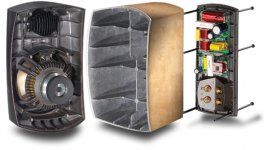
And then there's this: the Paradigm Signature series aluminum case (with 5mm thick walls).
An almost-all aluminum case would be terrible for my application (portable, wireless speakers), simply because this unit weighs 12 pounds and I want stereo pairs (and also the need to get a WiFi signal into the box).
Maybe keeping the resin enclosure and adding an aluminum-ribbed support structure (instead of the honeycomb sheet I previously thought of) would be the way to go.
Jeff
Attachments
- Status
- Not open for further replies.
- Home
- Loudspeakers
- Full Range
- Injection Molded Speaker Cabinets?