hi
i am in the process of firing up (probably not a good choice of words) my new f5. i have successfully biased one channel and am having difficulty on the second channel.
with both p1 and p2 turned fully counterclockwise, they each measure 0 ohms resistance. when i power up the channel, r7 reads around 190mv while r8 is at 0mv. turning p1 does not affect the voltage across r7, and p2 cannot be adjusted to result in more than about 30mv across r8. i have double/'triple checked the resistor values and they all seem ok. is it possible one of the transistors is bad?? any suggestions for troubleshooting this problem?
thanks
k
Kk,
as you adjust the trim/bias pot from zero ohms you can measure the voltage across it.
That voltage across the VR is the output device bias voltage.
Measure and see if the P1 change in voltage roughly matches the P2 change in voltage.
as you adjust the trim/bias pot from zero ohms you can measure the voltage across it.
That voltage across the VR is the output device bias voltage.
Measure and see if the P1 change in voltage roughly matches the P2 change in voltage.
found that r7 and r8 were damaged. i may have done this on hook-up. when i first connected that channel, i had the power on and connected the negative and positive a few seconds apart. the rest of the circuit seems to check ok. i have a couple of .47r resistors on order. the other channel is working very well.
thanks
k
thanks
k
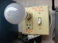
ALWAYS use the bulb tester to power up a mains powered project after EVERY modification.
There is no excuse for damaging new equipment due to laziness.
There is no excuse for damaging new equipment due to laziness.
plug your equipment into the bulb tester.
plug the bulb tester into the mains socket.
switch ON.
Does the bulb flash briefly, or a prolonged dim down, or glow bright?
plug the bulb tester into the mains socket.
switch ON.
Does the bulb flash briefly, or a prolonged dim down, or glow bright?
I read this a bunch of times....but I still don't know where to place the voltmeters cables and what to look for.
I will be greatful to anyone who could give a helping hand on these points :
I guess only P1 & P2 are concerned leaving P3 alone at mid setting......but .....I am not sure.
Iq is intensity, correct ? What values are we looking for ?
It is probably straight forward....once you know. The only thing I know is these settings are a must for the amp to deliver the better and I badly need help.
I will be greatful to anyone who could give a helping hand on these points :
I guess only P1 & P2 are concerned leaving P3 alone at mid setting......but .....I am not sure.
You mean P1 & P2 ?toss that and start with using your own head ; numbers are not relevant as meaning of procedure
- dial both pots to 0 ohms ( check with ohmmeter )
At the poles + & - of any condenser of the channel tested ? What value are we looking for ?Place one voltmeter across PSU caps ( best between + and - of PSU) to observe max voltage of PSU
On the + & - of the corresponding RCA ? What value are we looking for ? Zero ?Place one voltmeter at output - to observe offset
I am lost herePlace one voltmeter across one source resistors of output mosfets ; it doesn't matter which one .
I have no variac. Voltage on the PSU, is this taken at the output of the rectifier ?For test - slowly dial up Variac ( presuming that you have one , as man with many skills) up to full mains voltage , observing voltage at PSU ....... thinking about max cap voltage ( 25V as in FW ? ) , because with 0 Iq PSU is unloaded and voltage is maxed
Iq is intensity, correct ? What values are we looking for ?
Again what value are we looking for ?If nothing is smelling- leave Variac at full mains ;
what's important - Iq must be very low , offset is irrelevant in this moment .
now turn one pot one turn ( assuming that you have multiturns )
then turn other pot one turn
observe Iq and offset
What value for Iq is desirable ?Proceed one then second pot , again just one turn
observe Iq and offset
again one turn + one turn
now you are probably in range when you can see which pot is pulling offset in right direction - to 0 .
proceed iteratively with pots , while you set - say - 75% of desired Iq and zero offset
It is probably straight forward....once you know. The only thing I know is these settings are a must for the amp to deliver the better and I badly need help.
I'll try to answer some questions. There are a couple of recent threads on building
the F5 which should answer many of these:
Newbie help with F5
Another F5 Build
I reference the schematics from page 2 of the F5Turbo article, which should
correspond to the F5 v3 pcb from the store:
http://www.firstwatt.com/pdf/art_f5_turbo.pdf
Leave P3 alone in the mid-position until you know what to adjust.
Yes, begin by setting P1 and P2 to zero. Forget about clockwise or
counterclockwise. Simply adjust P1 and P2 so that the measured
resistances across R5 and R6 are close to zero.
For dc offset, measure at the amplifier output where you connect to say
the binding posts. Ideally it should be zero, but if can get it to a few
mV then that's fine.
The source resistors are R7 and R8.
The target Iq is about 1.3A, which you get when you measure about
0.6V across R7 or R8.
You can use a light bulb tester to make sure you don't have any runaway
current situation.
The voltage between the V+ and V- on the F5 PCB should be close
to say 46 to 50V. It'll drop a bit as you bias things up.
Hope this helps.
I'll try to answer some questions. There are a couple of recent threads on building
the F5 which should answer many of these:
Newbie help with F5
Another F5 Build
I reference the schematics from page 2 of the F5Turbo article, which should
correspond to the F5 v3 pcb from the store:
http://www.firstwatt.com/pdf/art_f5_turbo.pdf
Leave P3 alone in the mid-position until you know what to adjust.
Yes, begin by setting P1 and P2 to zero. Forget about clockwise or
counterclockwise. Simply adjust P1 and P2 so that the measured
resistances across R5 and R6 are close to zero.
For dc offset, measure at the amplifier output where you connect to say
the binding posts. Ideally it should be zero, but if can get it to a few
mV then that's fine.
The source resistors are R7 and R8.
The target Iq is about 1.3A, which you get when you measure about
0.6V across R7 or R8.
You can use a light bulb tester to make sure you don't have any runaway
current situation.
The voltage between the V+ and V- on the F5 PCB should be close
to say 46 to 50V. It'll drop a bit as you bias things up.
Hope this helps.
Sure it helps Dennis, I got to chew that for a while, thank you.
The voltage between the V+ and V- on the F5 PCB should be close
to say 46 to 50V. It'll drop a bit as you bias things up.
Is this the reason the amp board schematic shows -23V and + 23V going into the amp? I took classes in electronics almost 50 years ago, and I just want to be sure before I fry my amps.
unloaded rail (while amp is not fully biased or if you're testing just PSU) are in vicinity of Vac mult. with 1.41 [Vdc]
when you load it with amp , it's in vicinity of Vac x 1.25 [Vdc]
same as you're taller without shopping basket , shorter with it , especially when following your Missus in shopping
🙂
F5 is having two shopping baskets , one positive and one negative
so , that's why +/-23Vdc , sum of them being 46Vdc
when you load it with amp , it's in vicinity of Vac x 1.25 [Vdc]
same as you're taller without shopping basket , shorter with it , especially when following your Missus in shopping
🙂
F5 is having two shopping baskets , one positive and one negative
so , that's why +/-23Vdc , sum of them being 46Vdc
unloaded rail (while amp is not fully biased or if you're testing just PSU) are in vicinity of Vac mult. with 1.41 [Vdc]
when you load it with amp , it's in vicinity of Vac x 1.25 [Vdc]
same as you're taller without shopping basket , shorter with it , especially when following your Missus in shopping
🙂
F5 is having two shopping baskets , one positive and one negative
so , that's why +/-23Vdc , sum of them being 46Vdc
Thanks for clearing this up.
How do I adjust the DC bias at the speaker binding posts? One channel is .3V the other over .6V. I am getting the correct 0.6V across R7 and R8. PSU output is +/-24.1V.
Also, I've got another channel (I'm making 2 amps) that I've had running and made 'good' sound through a speaker. It's pair made smoke, unsurprisingly. That one I unfortunately started up before I knew what it meant to adjust bias. I've since used the correct procedure and it won't raise more than 40mV at R7/8 on the one that did work and didn't smoke. Where should I start troubleshooting? Thanks!
Also, I've got another channel (I'm making 2 amps) that I've had running and made 'good' sound through a speaker. It's pair made smoke, unsurprisingly. That one I unfortunately started up before I knew what it meant to adjust bias. I've since used the correct procedure and it won't raise more than 40mV at R7/8 on the one that did work and didn't smoke. Where should I start troubleshooting? Thanks!
You have two pots on each channel at the Gates of the output devices. You
tweak them to achieve both the right bias value but also the output DC.
On the blown channel, I would replace all the semis and measure all the resistors.
tweak them to achieve both the right bias value but also the output DC.
On the blown channel, I would replace all the semis and measure all the resistors.
Thanks for the help, Mr Pass!
What is the function of P3?
So I just 'play' with them and watch what turning each pot does to the final DC bias? Would it be an imbalance between the biasing of each of the mosfets or an overall bias level?You have two pots on each channel at the Gates of the output devices. You
tweak them to achieve both the right bias value but also the output DC.
Will do! I happen to have an extra set of semis for a pair.On the blown channel, I would replace all the semis and measure all the resistors.
What is the function of P3?
Last edited:
- Home
- Amplifiers
- Pass Labs
- Initial setting of F5 bias--help, please!