ok even if this solution is not the tube but, if it respects the dimensions requested by me then okay, maybe tell me some advice for the construction, in order to understand better
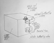
 Here is a ruff drawing of the idea, I'm afraid that I have no idea if it would work, I have no idea if anyone has done it before. It's just a variation of the rotary sub, but easier to make and using a box instead of anouther room. I think it's success would be very dependant on the volume of the box and the pressure that the fan could generate in the box, also the box would have to be well braced.
well from the image it is not clear very well for example if the box is empty, and the two 'ducts' in the foreground what are one is the fan and the other anyway as soon as I understand more I will start the construction, also why it should be similar to the tubeView attachment 1081151Ecco un disegno dell'idea, temo di non avere idea se funzionerebbe, non ho idea se qualcuno l'ha fatto prima. È solo una variazione del sub rotante, ma più facile da realizzare e utilizzare una scatola invece di un'altra stanza. Penso che il suo successo dipenderebbe molto dal volume della scatola e dalla pressione che la ventola potrebbe generare nella scatola, inoltre la scatola dovrebbe essere ben rinforzata.
yes GM then from your graph I did not understand if 10 hz corresponds to the largest volume and that is 320 dm3 this seems logical to me, I had seen the graph as soon as you posted itCan't fool Mother Nature, so seems reasonable to me that this chart would dictate box size.
The box would be empty, apart from strengthening braces ( although perhaps some speaker stuffing would increase the effective volume ) - it would just act like a reservoir. The lower duct is the one with the fan on it, feeding and pressurising the box, the upper duct is the exhaust. In neutral mode, both butterfly ducks would be half open, to produce positive sound wave, the butterfly valve on the intake would partially close, and the butterfly valve on the exhaust would open a bit more, thus reducing the amount of air in the box ( just like a massive driver cone moving out ), to produce a negative sound wave the butterfly valve on the intake would open more, and the butterfly valve on the exhaust would close slightly, thus increasing the amount of air in the box, just like a massive speaker cone moving in.well from the image it is not clear very well for example if the box is empty, and the two 'ducts' in the foreground what are one is the fan and the other anyway as soon as I understand more I will start the construction, also why it should be similar to the tube
ok ok I got it right then, anyway I will start building it and I will send you some construction feedback, maybe even in private massage to you or on the thread, one last thing, if I wanted to build in addition to this box, even a tube like mine was original idea, is the procedure to be followed always the same? that is, I put the tube folded on itself in a box and from one end of the tube I insert the fan hermetically?La scatola sarebbe vuota, a parte i rinforzi di rinforzo (anche se forse un po' di imbottitura degli altoparlanti aumenterebbe il volume effettivo) - si comporterebbe semplicemente come un serbatoio. Il condotto inferiore è quello su cui è montato il ventilatore, che alimenta e pressurizza la cassetta, il condotto superiore è lo scarico. In modalità neutra, entrambe le anatre a farfalla sarebbero semiaperte, per produrre un'onda sonora positiva, la valvola a farfalla sull'aspirazione si chiuderebbe parzialmente e la valvola a farfalla sullo scarico si aprirebbe un po' di più, riducendo così la quantità di aria nella scatola (proprio come un enorme cono driver in uscita), per produrre un'onda sonora negativa la valvola a farfalla sull'aspirazione si aprirebbe di più e la valvola a farfalla sullo scarico si chiuderebbe leggermente, aumentando così la quantità di aria nella scatola, proprio come un enorme cono dell'altoparlante che si muove.
Before you start building it, I'd like to point out that I have no idea if it will work; by all means give it a go but it might just sound like an industrial fan, after a lot of hard work, and expense.
- Home
- Loudspeakers
- Multi-Way
- Infrasonic pipe