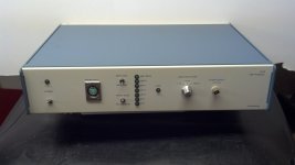
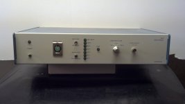
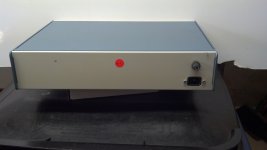
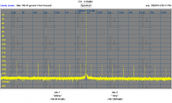
A long time ago I acquired this UltraAnalog JA-B Jitter Analyzer. I can find ZERO Information on it. Does anyone recognize it? have any info on it? It may have been custom built. I have it listed FS on eBay but I have very little info about it.
Attachments
That goes back to the dawn of digital audio. It really does work for 44.1 KHz. Its based on the standard jitter analysis system used in industrial environments. The core is a Crystal receiver and a good VCO as I remember. You won't find much on it anywhere.
I can't find your eBay listing.
I can't find your eBay listing.
I purchased the unit - but not had time to look into it much.
Its missing the input probe, and from what I can see the probe converts the Logic clock signal to Balanced Logic levels terminated into 75Ohms at the analyser.
Maybe the Probe head used a pair of Simple XOR's - the odd thing is that the analysers input circuit is not truly balanced - but one of the 'Differential' inputs is used (selected by the Edge Switch) for measurement... Really this should be a truly Differential input circuit - I might design and modify the unit - once I design a suitable circuit (Low noise).
BTW - this is the "Clock Analyser" not the SPDIF analyser.... and yes its only for 44.1KHz based signals, but still useful and can be extended with a little modification.
Does anyone know the history of the "Ultra Analogue" - who where the designers?
The PCB has JAB / SPC / RO which might be the design teams initials?
If I recall correctly, many years ago an audio electronics magazine published a Jitter analyser / modulator design - so I wonder if its by the same designers?
BTW - this is the "Clock Analyser" not the SPDIF analyser.... and yes its only for 44.1KHz based signals, but still useful and can be extended with a little modification.
Does anyone know the history of the "Ultra Analogue" - who where the designers?
The PCB has JAB / SPC / RO which might be the design teams initials?
If I recall correctly, many years ago an audio electronics magazine published a Jitter analyser / modulator design - so I wonder if its by the same designers?
Rémy Fourré V P of Engineering at UltraAnalog designed the jitter analyzer.
The design published in Audio Electronics October 97 was a collaboration between Fred Forssell and Bascom King.
Murray Allen,
Thank you for the info - a quick search on Rémy Fourré and I found this:-
Rémy Fourré was Vice President of Engineering at UltraAnalog. Born and educated in France, Dr. Fourré earned the US equivalent of a Bachelor's degree in computer design, a Master's degree in electronics, a Ph.D. in mathematics and mechanics, and a Ph.D. in applied mechanics. Dr. Fourré joined the fledgling UltraAnalog in 1988, developing the company's high-resolution 20-bit A/D and D/A converters. He also designed the test and calibration instrumentation used in producing UltraAnalog DACs (see Stereophile, June '93, p.57). Before working in digital audio, Dr. Fourré helped design a failsafe computer architecture that is the basis for automatic pilot control of French passenger trains. He was awarded three patents for these efforts. His most recent work was designing UltraAnalog's AES 20 digital input receiver module, and instrumentation to measure jitter in the digital interface.
Read more at Jitter & the Digital Interface | Stereophile.com
Is there any chance you still have a copy of the Audio Electronics October 97 article ?
Last edited:
Does anyone have a copy of Remy's Ultra Analog, Application Note AP-03:-
Jitter, Jitter, Jitter...
Fourre, Remy D.
Ultra Analog, Application Note AP-03
Jitter, Jitter, Jitter...
Fourre, Remy D.
Ultra Analog, Application Note AP-03
I have the AP-03 app note and the Forssell-King articles. I'll send you copies in the next few days when I have access to a scanner.
Schematics for the Forssell-King analyzer are here: http://www.forsselltech.com/media/attachments/Jitter_Detector_Input.pdf and http://www.forsselltech.com/media/attachments/Jitter_Detector_Output.pdf
Murray
Schematics for the Forssell-King analyzer are here: http://www.forsselltech.com/media/attachments/Jitter_Detector_Input.pdf and http://www.forsselltech.com/media/attachments/Jitter_Detector_Output.pdf
Murray
Murry,
Thank you, the information is much appreciated - I can send you funds via PayPal to cover any costs if required.
I have a long term plan / dream to offer a budget jitter analyser for the DIY community - it will be an external "adaptor" that can interface with a ADC/DAC design with internal DSP I'm working on, but I guess can be used with any decent ADC and PC software.
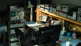
Basically a phase noise (jitter analyser) system that should cost no more then US$200 to US$300 for fellow DIy'ers - I have a Agilent / HP phase noise Rack system in the corner of the lab I can use to calibrate and confirm performance:-
https://dl.dropboxusercontent.com/u/86116171/Phase Noise test system Rack.JPG
Last edited:
Keith O. Johnson presented jitter analyzer with low BW PLL during his master class HIGH RESOLUTION COMPUTER AUDIO AES 129 Conv., 2010
Dimitri,
AES San Francisco 2010
Master Class M2
Thursday, November 4, 2:30 pm — 4:30 pm (Room 206)
M2 - High Resolution Computer Audio
AES San Francisco 2010 Master Class M2: High Resolution Computer Audio
Where any schematics published or just a conceptual discussion?
The UltraAnalog Jitter Analyser also appears to be based on the concept of Demodulation via a low B/W PLL, the odd thing is that the 36 paralleled capacitors (36x 2.2uF) in the Loop filter appear to be Z5U and its my understanding that the Z5U dielectric is as bad as you can get (lossy) and not what you would expect to see in a Low B/W loop filter.. so I'm trying to understand the designers thoughts... why go to all the effort of using x36 Capacitors of such poor dielectric performance?
https://dl.dropboxusercontent.com/u/86116171/ceramperf.pdf
With every critical parameter within a Low B/W loop filter circuit the Z5U dielectric would be the very worst choice - now I'd understand if the caps where COG and hence the paralleling to achieve the larger required value...
Last edited:
The Forsell-King design is an implementation of a standard solution for data link analyzers and is pretty good down to the limit of the internal oscillator. its desinged to look at the data on the SPDIF link. It could easily be revised with current SPDIF receivers and multiple clocks to work up to 192KHz and have a lower noise floor. For looking at internal clocks you would do it differently and in any case the noise floor will be higher than current state of the art. Also, finding the voltage controlled crystal oscillators will not be cheap.
One of my blog entries is on how to use an FM tuner for jitter analysis. Its effectively not a lot different and pretty adaptable.
One of my blog entries is on how to use an FM tuner for jitter analysis. Its effectively not a lot different and pretty adaptable.
I can ask Keith about his jitter analyzer. I'll let you know what I find out.
Thank you Demian. I attended presentation but have no pictures 🙁. I remember Keith listened to the PLL filter output.
finding the voltage controlled crystal oscillators will not be cheap.
I can design ultra low noise VCXO's "cheaply", and across the audio B/W internal feedback can be used to lower the phase noise and provide amplitude stabilisation.
- I have a Agilent / HP phase noise Rack system in the corner of the lab I can use to calibrate and confirm performance:- [url said:https://dl.dropboxusercontent.com/u/86116171/Phase%20Noise%20test%20system%20Rack.JPG[/url]
I have same here, although most of it has been re-purposed😉
Attachments
Murray,
Brilliant 🙂 yes indeed, originally I had a 89441A in the rack but replaced it with the 3561A as the 89441A is more useful on the lab bench - nice lab you have there.
I'm always battling trying to measure Phase noise across the Audio Bandwidth ""Offsets" with adequate dynamic range.. hence the interest in developing such a unit...
Which signal(s) would be most useful for measuring its jitter in an ADC or DAC?
I have a Yokogawa jitter analyzer (TIM). But not sure which are the most important signals to measure of a finished product.
SPDIF or ??
THx-RNMarsh
I have a Yokogawa jitter analyzer (TIM). But not sure which are the most important signals to measure of a finished product.
SPDIF or ??
THx-RNMarsh
Last edited:
Probably looking at the output of the DAC will show what is actually important. Looking upstream is good for finding sources of problems but if its not in the output of the DAC its probably not important.
For example, this is the output of a very modest ($70) USB DAC I got from China via eBay. Its the usual 16 bit Jtest presented similarly to Stereophile. This analog output is virtually identical to a pure digital link with no jitter. In this case I'm not sure what is to be gained from lower jitter.
For example, this is the output of a very modest ($70) USB DAC I got from China via eBay. Its the usual 16 bit Jtest presented similarly to Stereophile. This analog output is virtually identical to a pure digital link with no jitter. In this case I'm not sure what is to be gained from lower jitter.
Attachments
Which signal(s) would be most useful for measuring its jitter in an ADC or DAC?
I have a Yokogawa jitter analyzer (TIM). But not sure which are the most important signals to measure of a finished product.
SPDIF or ??
THx-RNMarsh
Measuring the MCLK input at the DAC / ADC is the critical point.
I suspect the Yokogawa jitter analyser will be rather limited in this application normally these type instruments have 50pS to 100pS time interval resolution. With a competent design Phase noise components should be less then a pS.
- Status
- Not open for further replies.
- Home
- Design & Build
- Equipment & Tools
- Info for UltraAnalog Jitter Analyzer
