I am using an LCL filter after my rectifier and I want to use a voltage regulator as well. Can I put the regulator after the cap or does it have to be at the end of the filter chain?
If the filter is CLC no problem. But LCL isn't good. Regelators linear or switching dislikes be hooked directly to an inductor. Always need a capacitance.
What is the minimum size of cap?If the filter is CLC no problem. But LCL isn't good. Regelators linear or switching dislikes be hooked directly to an inductor. Always need a capacitance.
It depends. If linear IC, see the manufacturer's recomendation. In general, the larger, the better. For switching, you will need to use several paralleled; for example a 1mF // 47uF // 1uF // .1uF. Mainly if is of the buck and his "sons": This is because the current waveform is a triangle over a rectangle. So large voltage ripples are expected in the bulk storage capacitor.
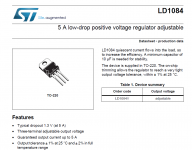
it is a linear regulator for a non-switching p/sDepends on the regulator.
Just as an example, here is the mfr spec for the LM317.
Driven from a voltage source, input 0.1uF, and outout 1.0uF.
The voltage source also must also deliver the needed current
within the ripple limits for 1/120 seconds, so a certain amount of
bulk input capacitance is also necessary. See post #8.
Your own circuit may vary considerably, but the requirement is there, since a regulator is
a feedback amplifier. Beware of insufficient load capacitance, which might cause instability.
Attachments
Last edited:
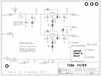
Maybe the Tuba PCB might be slightly illustrative? It's used in SIT / VFET / Ship Of Theseus power amps, to provide clean DC power to two amplifier channels, using a pair of high current voltage regulator chips in an arrangement similar to dual mono. The amp channels are Class A and each one draws about 1.8 amps.
OBTW there's a thread about Tuba here on the Forums.
_
OBTW there's a thread about Tuba here on the Forums.
_
Attachments
Here is a simplified schematic of the LCL filter that I want to use except for two things: the rectification would be a full wave bridge and there would be no second cap. My goal is to put the v. regulator after the first cap. Is this possible?
Attachments
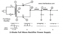
I found a simplified version of my proposed schematic. See below.I can't yet, but I will in a couple of days.
- Home
- Amplifiers
- Power Supplies
- inductor p/s and voltage regulators