Try upping the bias to 3A.
Magura 🙂
EDIT: 3.65V is a little high on the JFET ? As I recall I had mine running quite abit lower to keep it liniar.
Magura 🙂
EDIT: 3.65V is a little high on the JFET ? As I recall I had mine running quite abit lower to keep it liniar.
O.K. It has more gain 😀 But, still have a distorted square wave 
3.5V on the jfet Drain, 2.9A, Gain about 12.5...
3.5V on the jfet Drain, 2.9A, Gain about 12.5...
I have just compared your schematic with my amp, and the only thing that differs now (besides the type of inductor and your voltage divider) is you cascode modulation cap. You have 680uF and I have used 2*100uF lytics plus 2*1uF film.
I see no reason to suspect your voltage divider ???
Magura 🙂
I see no reason to suspect your voltage divider ???
Magura 🙂
No. And it is a real 50 ohm out. If I forget to terminate it the readout gives me 1/2 the real output voltage. Adding a 50 ohm terminator makes the readout correct... I'm also driving it strait into the gate with a 200k ohm to GND. No feedback. The "tilt" is not measureable on the source R, only at the cacode Drain. That Cascode filter cap is actually a 470 OsCon and it has a .1 Film on it too. I'm saving my 680 BG for the final build. I have tryed up'ing the value already, to no avail...
I've given it some thought also. I should be able to calculate the angle versus the inductance and load but the math eludes me at this moment. It should be something like I=L*dV*dT??? Not in the mood right now. Guess I gotta look it up Ha?
I also have not given up on the low output cap value thing, I have a biggy I will try in a few minutes...
BTW, did you say you are doing something like 50-100 Watts on your cascode device? My H.S. is a .35 D/W and yesterday I was probably burning 90 Watts or so total...

I've given it some thought also. I should be able to calculate the angle versus the inductance and load but the math eludes me at this moment. It should be something like I=L*dV*dT??? Not in the mood right now. Guess I gotta look it up Ha?
I also have not given up on the low output cap value thing, I have a biggy I will try in a few minutes...
BTW, did you say you are doing something like 50-100 Watts on your cascode device?
My H.S. is a .35 D/W and yesterday I was probably burning 90 Watts or so total...O.K. The low freq square wave distortion is not being caused by the output cap being to small. 33,000uF+ is not small and its still there
Well, I meant for you to try less than 680uF for the cascode modulation cap...like 200uF or the like.
I have been running my IRFP240 devices at 150W with reasonable reliability. I got the first faillure after like more than 500 hours of operation. This was achieved with substantial heatsinking 😀
Do you have a BOZ or the like to try as a buffer?
Magura 🙂
I have been running my IRFP240 devices at 150W with reasonable reliability. I got the first faillure after like more than 500 hours of operation. This was achieved with substantial heatsinking 😀
Do you have a BOZ or the like to try as a buffer?
Magura 🙂
flg said:O.K. The low freq square wave distortion is not being caused by the output cap being to small. 33,000uF+ is not small and its still there
According to my experience, the low frequency output is attenuated, not distorted, if the output cap is too small.
This is getting interesting 🙂
Magura 🙂
Dumb question: ac or dc coupling selected at the input of your scope? I spent some time with similar issues that ultimately ended up being the time constant of the unintended differentiator at the input of my scope. (Problem below 20hz only)
Just a thought?
XL in your choke should be >5X (10X) your load impedance for reasonable performance at the lowest frequency of interest. imho..
Just a thought?
XL in your choke should be >5X (10X) your load impedance for reasonable performance at the lowest frequency of interest. imho..
kevinkr said:Dumb question: ac or dc coupling selected at the input of your scope? I spent some time...
No, not a dumb question... BTDT (Been there Done That) 😀
DC. My AC mode will start to exhibit the same characteristics below 30Hz or so
Trying to dig out the 5V over 6mS shift now. Not sure of the math 😕
I have seen this type of distortion with an output cap being to small 😀 But, like you where thinking, it shouldn't be to small at the value I started with??? However, with this inductor in the circuit, I beleive I can have the same type of problem...Magura said:
According to my experience, the low frequency output is attenuated, not distorted, if the output cap is too small.
This is getting interesting 🙂
Magura 🙂
As to attenuation, well, when your looking at 1 pure frequency sine wave, your vision is narrowed. Thats why I'm using square waves. A Sine wave looks fine! I'll bet a THD measurement would show a similar degradation in the low freqs...
The inductor formula I was looking for is v=Ldi/dt but I haven't figured out how to apply it to the problem. I was hoping the voltage change would fit into this formula to prove the inductance was not large enough??? Hmmm
XL = 2piFL..
Where XL is the inductive reactance, pi is pi, F is frequency and L is inductance in henries.
Your inductive reactance should be about 5 - 10X the load resistance for good LF performance - more may not be that unreasonable.
Don't loose sight of the possibility that it is unrelated to this issue, check the power supply caps while driving the amplifier at a low frequency.
The formula you sited is correct, for a sinewave, creating an effective impeadance in an inductor. Provided there is no saturation effects going on. It works out that something like 10Hz will generate something like 8 ohms with this inductor. And I do see a -3db response (1/2 the voltage out) at about 6Hz + or -, when using a sine wave input.
However, what I'm seeing is a distorted square wave. Granted, it's not music, but, music is not a (1) sinewave either. Herin lies the falicy of relying on, or comparing specs with, a standard THD test, which uses a sinewave as a source. Atually, a square wave is the sum of a fundamental frequency, a third harmonic of 1/3 the fundamental amplitude, a 5th harmonic of 1/3 the 3rds amplitude, a 7th harmonic of 1/3 the 5ths amplitude, and so on. A whole group of frequencies that magically, thanks to mother nature, sum to what we call a square wave. Incidently, this could be looked at as 33.3% distotion of the fundamental sine wave. This is not so unlike music. A group of frequencies summed from many instruments and or vocals to form a very complex, constatly changing wave form.
But, when I put a square wave in, a distortion takes place in the circuit that makes it change into a half sawtooth looking wave??? It extends all the way up to about 1k decreasing in distortion as frequncy climbs. Actually I would also expect a gain change as the inductors impeadance goes up but, I do not see that. Can anyone explain this phenomina?
I'm going to try some THD tests next.
Whats the bandwidth of the amp? Will it produce the higher frequencies? If its not to high, you won't be seeing a square wave. It won't be able to reproduce the high frequencies and it will wind up looking like a saw tooth wave.
Now wait a minute....you have no global negative feedback...try adding some 10 db of feedback and see what you get,perhaps add a 20 to 50pF cap across the feedback resistor.
As I recall I have used a 50pF cap...
Magura 🙂
As I recall I have used a 50pF cap...
Magura 🙂
davidallancole said:Whats the bandwidth of the amp? Will it produce the higher frequencies? If its not to high, you won't be seeing a square wave. It won't be able to reproduce the high frequencies and it will wind up looking like a saw tooth wave.
Well, that I beleive is at least somewhat correct. If the bandwidth was "cut-off" between the fundamental and the 3rd harmonic frequency, I would see a sine wave of the fundamental freq. Without all those odd harmonics in the progression I suggested (or something close to what I suggested) there would not be a square wave. However, most of us have experienced the square wave rounding off due to limited bandwidth and it generally does not look sawtooth. But something inbetween a square and a sine 😀
To answer your question davidallancole, I'm not totally sure what the bandwidth is. It does a good job up to 200kHz. After that the positive portion of the waveform starts to become higher in amplitude and looks distorted. I became somewhat "afraid" of bad things happenning beyond 300k so I gave up on going any higher.
 Probably some kind of miller effects giving feedback and poles and stuff.
O.K. Between 200k and 700k there is a little peaking, using a sine wave input. The actuall -3db point is 1.05mHz  and the sine wave looks good up there. 😀
This is open loop, with 4Vpk (8Vpk-pk) output into a 7.5 ohm load. Not bad if I do say so myself 😀
and the sine wave looks good up there. 😀 This is open loop, with 4Vpk (8Vpk-pk) output into a 7.5 ohm load. Not bad if I do say so myself 😀
Sounds like the bandwidth is excellent, the only other thing I could think of without being there is are your probes calibrated for the square wave? You know that little square wave that is generated on the scope you can use to calibrate the probes so they don't over shoot or slope to much.
I got myself thinking 😱 with that square wave, harmonic post up there. Actually describing this stuff is pretty difficult even if you do know what your talking about 😕 But, I think I stumbled in my own mess here...
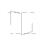
Trying to use a load as low as 8 ohms on a common source amp like this reduces optimum gain. I have used bulbs and big Rs on this design several months ago and this is true. That's why I said I expected the gain to go up with frequency due to the inductors Xl going up with frequency. But it's real flat, gain wise, from 30Hz on up to a Meg except for the low Q peaking. Like I said, lower -3db @ 6-7Hz! But, the square wave is full of multiple frequencies. And down low, the fundamental and low order harmonics of the Sq Wave could be operating in lower gain while the higher order harmonics are operating in a higher gain... Hence sq wave distortion The average peak level of the sq wave is the same as the sine wave would be. I'll show a pic... Does this mean there is some frequency dependant gain variation causing the distortion, due to the rising Xl???
Trying to use a load as low as 8 ohms on a common source amp like this reduces optimum gain. I have used bulbs and big Rs on this design several months ago and this is true. That's why I said I expected the gain to go up with frequency due to the inductors Xl going up with frequency. But it's real flat, gain wise, from 30Hz on up to a Meg except for the low Q peaking. Like I said, lower -3db @ 6-7Hz! But, the square wave is full of multiple frequencies. And down low, the fundamental and low order harmonics of the Sq Wave could be operating in lower gain while the higher order harmonics are operating in a higher gain... Hence sq wave distortion
The average peak level of the sq wave is the same as the sine wave would be. I'll show a pic... Does this mean there is some frequency dependant gain variation causing the distortion, due to the rising Xl??? Attachments
- Status
- Not open for further replies.
- Home
- Amplifiers
- Pass Labs
- Inductor Loading Adventures