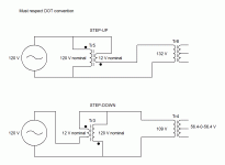
If you reverse one of the winding then you'll end up with output voltage higher than input voltage while the opposite is needed.
sorry forgot to say" reverse the input/output connections for step down". since its windings are all in phase, it works exactly like an autotransformer can boost and buck One end of the winding is usually connected in common to both the voltage source and the electrical load. The other end of the source and load are connected to taps along the winding. Different taps on the winding correspond to different voltages, measured from the common end. In a step-down transformer the source is usually connected across the entire winding while the load is connected by a tap across only a portion of the winding. In a step-up transformer, conversely, the load is attached across the full winding while the source is connected to a tap across a portion of the winding.https://en.wikipedia.org/wiki/Autotransformer
Last edited:
If the secondary is center tapped 62-0-62, then it's difficult to remove some of the winding's from it. Unless you want to rewind the secondary's. Ad to the primary's ,as suggested is the way to go.
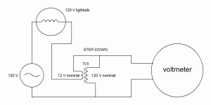
You may use a 120V-12V transformer in front of your power transformer and use it as an autotranformer. 12V winding must have nominal current of the 120V winding of the big transformer.
Audiofan's post23 diagram and his description in post21 are both correct.
This is the correct way to wire an autotransformer.
Use a Mains Bulb Tester to protect until you PROVE your wiring is correct.
This is the correct way to wire an autotransformer.
Use a Mains Bulb Tester to protect until you PROVE your wiring is correct.
Could you add the diagram for a step up autotransformer?missing GIF
stepping up the primary V is a bad plan with commercial mains xfmr
they are already wound for B pushing the edge of core saturation with nominal, labeled line V
even standard hi line tolerance testing can give 2x more primary magnetizing current
additionally 60 Hz mains gives a little more V*t margin than 50 Hz mains countries - I've had to up fuse A rating 2x over what worked in the lab, US wall outlet, when testing product with 50 Hz and high line V even with dual primary 50/60 Hz speced "international" mains xfmrs
Last edited:
Using an autotransformer to step up the mains voltage does not push the transformer any further into saturation.
Using too few primary turns is the main cause of excessive flux in the primary.
Step up does not alter the primary turns.
Using too few primary turns is the main cause of excessive flux in the primary.
Step up does not alter the primary turns.
not the auto transformer itself - but feeding the primary of a following transformer with 20% boosted line V could be problematic
jcx is right, if you use a step-up configuration to increase voltage at the primary of a transformer ... the transformer will have a higher volt/ turn ratio at the rimary and a higher flux in the core .. will go to saturation or close to ... and wiil increase magnetisation current ... not a good thing at all
Attachments
missing GIF:

Ooooh, I think I actually have a pair of transformers on hand that I can use to test this scheme!
Thanks for posting the circuit diagram. I was not sure just how to connect the additional transformer with low voltage secondary...
I'm learning a lot in this thread.
Here's a question: for the winding that is doing the bucking or boosting of the mains AC voltage - is it ever possible to use a separate winding on the SAME CORE and not another transformer? I can't quite wrap my head around what would be happening in that case... but it seems this might be used as the "extra turns" that was talked about earlier in the thread. Is that correct?
It just so happens that this transformer has two extra secondary windings: one 0-12Vac and another 16.5-0-16.5. Unfortunately I do not know the current rating for these windings (or even the wire diameter used) but in general I am curious if this approach could work.
In a transformer voltage is simply proportional to the number of turn.
If you put two winding in serie you may have:
1- consecutive winding that will give a bigger number of turn and a bigger voltage
( sum of voltage )
2- opposing winding that will leave a reduced number ofturn and a lower voltage ( difference of voltage )
Maximum current for these connection is always limited the nominal current of the lowest current of the windings
In many equipement made for many country you have a voltage selectin switch ... these switch works according to this technique
I have a couple of 500VA transformers that have a center tapped 62-0-62 secondary and a single 115VAC primary. The secondary voltage is a little too high, and I would like to reduce it by around 5-10%.
Thanks to this Wikipedia article, I see that a voltage divider can be created with two inductors.
Can I simply add an inductor in series with my transformer primary to form a voltage divider, thus reducing both primary and secondary AC voltage? Will the inductance of the primary change with the amount of current drawn? Are there practical pitfalls/problems with this approach?
adding an inductor is a bad idea....
you have two options...
1. add additional primary turns and series connect in phase to lower secondary voltage.
2. add additional bifilar secondary turns and series connect them as bucking windings.
take your pick...
don't mix secondary windings between primary and secondary - sec-sec insulation and spacing is almost never adequate for safety separation from mains
as mentioned is sometimes possible with toroids to add a few winding turns external the provided insulation - with right wire, perhaps added sleeving you could have enough to count as double insulated/reinforced safety rated separation
complete over wrapping with added tape layers risks limiting heat dissipation
^yes....
with my option 1, do not forget to use a series lamp tester, phase is correct when the lamp is hardly lit,
you can wind a few test turns, say 5 turns and measure the voltage to get the turns per volt ratio...
with my option 1, do not forget to use a series lamp tester, phase is correct when the lamp is hardly lit,
you can wind a few test turns, say 5 turns and measure the voltage to get the turns per volt ratio...
Wiring 120v-to-12v transformer like a *step-down* autotransformer is suboptimal: it reduces voltage applied to its primary and reduces voltage at its secondary, that makes output voltage regulation worse than it could be. Is there a point of doing that?sorry forgot to say" reverse the input/output connections for step down". since its windings are all in phase, it works exactly like an autotransformer can boost and buck One end of the winding is usually connected in common to both the voltage source and the electrical load. The other end of the source and load are connected to taps along the winding. Different taps on the winding correspond to different voltages, measured from the common end. In a step-down transformer the source is usually connected across the entire winding while the load is connected by a tap across only a portion of the winding. In a step-up transformer, conversely, the load is attached across the full winding while the source is connected to a tap across a portion of the winding.https://en.wikipedia.org/wiki/Autotransformer
Last edited:
Wiring 120v-to-12v transformer like a *step-down* autotransformer is suboptimal: it reduces voltage applied to its primary and reduces voltage at its secondary, that makes output voltage regulation worse than it could be. Is there a point of doing that?
The only reason to do so is to get lower output voltage from a transformer you already have.. and save money..
The whole point of using an auto-transformer is to ADJUST the mains voltage to suit the load that is required to be driven.Wiring 120v-to-12v transformer like a *step-down* autotransformer is suboptimal: it reduces voltage applied to its primary and reduces voltage at its secondary, that makes output voltage regulation worse than it could be. Is there a point of doing that?
If one has a 230Vac transformer and the Mains is habitually round 245Vac, then one can reduce the mains voltage down to around 230Vac efficiently by using an appropriate auto-transformer.
Similarly if one has a 240Vac transformer, but your mains is regularly 220Vac, one can increase the voltage to suit that 240Vac load by using an appropriate auto-transformer.
One does not use a step up auto-transformer to overdrive the load as suggested in this reply
One can even use an auto-transformer to convert between 115Vac and 230Vac for mismatched mains supply voltage and mains powered appliances.stepping up the primary V is a bad plan with commercial mains xfmr
they are already wound for B pushing the edge of core saturation with nominal, labeled line V
even standard hi line tolerance testing can give 2x more primary magnetizing current
Last edited:
- Status
- Not open for further replies.
- Home
- Amplifiers
- Power Supplies
- inductor in series with transformer primary to reduce secondary voltage?


