I felt that this Important topic deserves it's own dedicated thread. I credit just a guy for initially arousing my interest in this, others for their inputs, & Josh Ricci @ DataBass for providing good tests & data. For those that havn't been following, the discussions recetnly sprung up in the 16 hz for church organ thread http://www.diyaudio.com/forums/subwoofers/272833-16-hz-church-organ.html
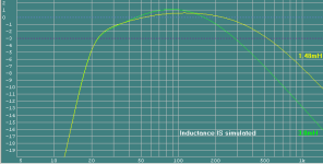
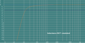
Out of curiosity, i simmed the same driver with the EXACT same data for both the driver & box, except for changing the inductance of one of them. To do this i only had to create a new instance of the driver file, so i could then load both into WinISD to compare them. WinISD has a very useful feature, whereby you can click on a tab to account for inductance, or not !
Interestingly, it certainly does appear to make a difference, in this sim not a great deal, but it's there. From this, i "expect" higher inductance drivers to exhibit an even greater difference, & starting even lower down the f scale.
Also by changing values in the Voice Coil Temp Rise tab in real time, which effects Re, allows you to see the combined differences both make together.
I look forward to more stimulating etc discussions & tests etc. Plus it would be great if for eg HornResponse etc could be made to alter Inductance in real time.
Attachments
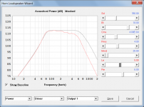
Plus it would be great if for eg HornResponse etc could be made to alter Inductance in real time.
You mean like this?
Attachments
I posted a reply in the 16-Hz organ thread but I suppose it really belongs here, now that this thread has started.
I gather that that the Thiele-Small model starts to fall apart (to a small degree) when inductance, resistance, (and I suppose all other parameters) vary with frequency. And more surprised that inductive reactance, which is pretty small at low frequencies matters.
I have no trouble intuitively expecting mechanical parameters to vary although surprised to hear electrical inductance and resistance can vary (saturation or compression effects excepted). Other instances or devices where they vary?
Is it because the underlying theory of electrical analogies to mechanical and electrical parameters in speakers has no analogies where inductance, etc. vary with frequency? Or because, well, all models are a bit crude?
I find it scientifically distasteful to finagle parameter values until the resulting output kind of matches measured results in the absence of understanding just what is going on. Not a video game.
Ben
Inductance absolutely does make a big difference in a sim, especially if it is a large value for Le.
Some drivers can't be simulated accurately, that was the point of the discussion in the 16 hz thread. Until yesterday I thought the effect was solely due to inductance, but here's what I wrote in the 16 hz thread today.
When I'm wrong I admit it. When searching for the UM18 measurements on data-bass I saw the familiar "inductance hump", which shouldn't be there in such a low inductance driver. This means I may be wrong about inductance being the sole cause of the issue. The cause may just be very large and heavy voice coils, although at this point I don't want to speculate too much. However hopefully I can be excused for correlating this effect with inductance, since 99 percent of this type of ultra high excursion driver with very large and heavy voice coils also has ultra high inductance.
Anyway, the method still works on this type of driver. It works great to sim the UM18 with it's "inductance hump" too, even though it's not a high inductance driver and the hump doesn't look like it's caused by inductance.
Anyway, the correction method works great, but it's back to the drawing board to find the exact cause of the issue that makes this type of driver not sim right, which is useful in identifying them without seeing them measured first, which is one of the biggest advantages to the correction method. If Le:Re is higher than 1:1 you can bet it won't sim right, but now there are a couple of identified driver will Le:Re much lower than that, that also need correction.
Anyway, adding artificial Le to a sim to try to accurately sim these big drivers does not work, but as alluded to above, I do have a method that does work really well, 100 percent of the time, for all drivers of this type in all enclosure. The correction method is not perfect, it could use refining but I don't have time to play with it and it's a lot more accurate than just ignoring these effects and running the t/s parameters provided through a regular sim.
I find it scientifically distasteful to finagle parameter values until the resulting output kind of matches measured results in the absence of understanding just what is going on. Not a video game.
Ben
The 3 point complex inductance model by Leach (and at least one other complex inductance model authored by somone else) has t/s parameters specifically to describe frequency dependent resistance and frequency dependent reactance.
No this is NOT a video game, what I am doing is forcing a simulator that cannot accept these parameters to consider them. I told you that already. It's not a perfect method but it works 100 percent of the time on all drivers of this type in all enclosures.
Science is the process of testing a theory and coming up with enough evidence that the theory works that it cannot be disproved. IF it is disproved, the theory is over and done. What I am doing is science, what you are doing is complaining. Disprove the theory if you like. Good luck with that.
Your hatred of simulators and simulations is well documented. Even though you don't use simulators and don't trust their results even when shown mountains of proof that sims match measurements. Simulators are the BEST tool we have to estimate performance of a driver and they are REALLY good at it. There are very few exceptions in which they fail at what they are made to do, this is one of them, and my method corrects that.
The problem, Ben is that you would like simulators to do things they are not made for, like estimating in room response or simulating the type of drivers we are talking about here without being able to accept complex parameters. Another problem is that you've heard bad designs (like max flat ported boxes) that sound terribly boomy in room, and just because the design was created in a simulator, you blame the simulator, not the bad design. Max flat is generally not appropriate for using in a room with any amount of room gain - especially when you prefer the sound of a rising response of a sealed box as you do. As I've told you several times, you can design that response curve shape into a ported box too, and if you did you wouldn't be able to tell which was sealed and which was ported in a blind test until you turn them up really loud and the sealed box can't keep up anymore. It's not resonances you hate when you hear a design, it a bad design that you hate, and unfortunately you haven't been able to distinguish bad designs from characteristics and mistakenly blame things like simulators and resonances as a whole when the problem is really just bad designs.
Since I've told you all this several times now, you either are not reading or not understanding what I am telling you, since you continue your all out assault of simulators, simulations, and resonances.
Last edited:
Hi Zero D,
JAG has been beating on this for a while, here are some additional links,
on the avs forum: DIY Speakers and Subs - AVS | Home Theater Discussions And Reviews
and on diyaudio,: http://www.diyaudio.com/forums/subwo...urately-2.html
avsforum LTD02 picked up on this, and applied a reduction to Bl, at times in combination w/ an increase in Le. This looks like a promising approach as it addresses parameters that are known to change w/ frequency, and high power application.
The bad thing is that sofar there is no method that can be applied universally, so we are back to more extensive empirical testing to get the data for entry into the simulators.
Regards,
This looks like a promising approach as it addresses parameters that are known to change w/ frequency, and high power application.
Yes, that's scientific, for want of another word to describe acting rationally, rather than by guesswork.
In practice, you CAN use guesswork and accidentally get reasonable predictions some of the time because some of the parameters in the T-S model behave co-relatedly. That's you-know-whose method. But it has no merit for advancing understanding of what is going on with higher inductance drivers.
Ben
Ben, if you actually read the links you would see that this is not guesswork and it's not accidental and it doesn't work "sometimes", it works 100 percent of the time on all high inductance drivers in all enclosures. I noticed a few years ago already that the higher inductance drivers didn't measure the same as the sims predicted. I also noticed that the effect looked exactly like the effect of adding additional Re to the sim, as I am always doing to see the estimated effect of power compression. The response curve humps up around the impedance peak(s) and rolls off everywhere else. So I tried adding a bit of Re, then adding a bit of power to offset the added Re losses, and it worked. All the time. On all high inductance drivers. In all enclosures, sealed, ported, tapped horn, front loaded horn, every enclosure type I could get a high quality measurement and box dimensions on.
And coincidentally, at a glance (without knowing too much about the subject) this seems to be exactly the point of the 3 point complex inductance parameters and simulators that can accept them, frequency dependent Re and reactance are actual t/s parameters. I'm just forcing a simulator that won't accept these parameters to consider their effect.
I'm not a driver expert, and I really don't think I need to be. Sometimes you don't need to completely understand WHY a problem is happening to find a cure for it. Actually this happens all the time in science.
While it would be nice to know exactly what is causing the issue, there's plenty of data to guess which drivers will be affected (ones with very big and heavy voice coils, especially if their inductance/resistance ratio is 1:1 or higher), and the correction method works very well 100 percent of the time. What else do you need?
And seriously, why do you even care about any of this? You don't believe in the validity of simulations in the first place, despite being presented with mountains of evidence, so why is this particular issue so important to you? And if you want to disprove it so badly, why don't you provide some evidence of your own to show it doesn't work? I've shown plenty that shows it works very well. You spend most of your time on this forum attempting to discredit well known science (in the form of math done by simulators) and now you are complaining that I'm not scientific enough?
Last edited:
The bad thing is that sofar there is no method that can be applied universally, so we are back to more extensive empirical testing to get the data for entry into the simulators.
Regards,
Actually I do apply the correction method universally on any driver that obviously needs it.
To explain that better, the exact same tweak is applied to every driver that has Le:Re ratio of 1:1 or higher. The only problem here,which I just discovered yesterday, is that there are some drivers with considerably less Le:Re ratio of 1:1 that also need that also need to be corrected, as they suffer from the same issue. But so far, all the drivers I've identified that have this issue have really big, heavy voice coils, and almost (but not quite) 100 percent of them also have very high inductance.
There needs to be more work done to find out EXACTLY which drivers need the tweak just by looking at published specs and/or voice coil physical data (although we already know that high inductance drivers need the tweak 100 percent of the time, I've never seen a high inductance driver that didn't suffer this issue, but now I've found a couple of lower inductance drivers that are also afflicted). AND the method could be a bit further refined so it's not exactly the same simple tweak applied to all afflicted drivers, in other words, it could be improved to be a bit more accurate. But as it is it's quite good already and I've posted a bunch of examples showing this in the links you provided.
@ David McBean
Yes, exactly like that ! Sorry i forgot about that feature, as i havn't played with it lately. I tried it earlier & it sure works. Good job 🙂
@ tb46
Thanx for the info & links, which i'll check out. EDIT, the link to http://www.diyaudio.com/forums/subwoofers/subwo...urately-2.html is broken ? Also which LTD02 thread/s ? as there appear to be many !
@ just a guy
Adding Re & reducing Le etc, in Actual real time & with powered enclosures, sounds like a task that for eg AceBass could do 😉
Last edited:
Hi Zero D:
I copied the links from a PM I wrote. Well, here we go again: the respective thread @ avsforum (diyaudio_just a guy is avsforum_diy speaker guy), start @ Page 9:
HzHorn - Page 9 - AVS | Home Theater Discussions And Reviews
and one more try @ JAG's thread here on diyaudio:
http://www.diyaudio.com/forums/subwoofers/264052-simulating-high-inductance-more-accurately-2.html
Regards,
Hi just a guy,
Just being aware that there is a problem w/ drivers having "big, heavy voice coils" is a definite plus. We cannot fix what we don't know. So, I definitely appreciate your efforts on this subject.
I think your way of looking @ data-bass.com data will help.
We're just not at the point where we can say, e.g.: for all overhanging voice coils we have to subtract 1.5% of Bl for every mm of Xmax, add 0.2mH to Le for every 1mm of Xmax, and recalculate Re for xxxC.
If we were able to do that than David McBean could integrate the data into an advanced power compression model.
Regards,
We're just not at the point where we can say, e.g.: for all overhanging voice coils we have to subtract 1.5% of Bl for every mm of Xmax, add 0.2mH to Le for every 1mm of Xmax, and recalculate Re for xxxC.
Absolutely right, and it would be nice to have a really exact method like that although I don't think it's going to ever be possible to get that accurate based on just published specs and info.
For example the TC Sounds drivers don't seem nearly as affected despite their big heavy voice coils and high(ish) inductance.
Since there's a lot of difference in coil sizes (width and length), number of layers, coil styles (overhung, underhung, split, xbl, etc), so many different motor styles and geometries and dozens of other differences, it might be hard to track down exactly what is causing the issue to this degree of accuracy. And since it's impossible to know a lot of these details unless you take a driver apart the info is hidden anyway.
It might be easier to just use REW (or similar software) to generate the complex t/s parameters and author a simulator to accept them (a simulator like Hornresp that can simulate more complex enclosure than Unibox).
Anyway, for now, my super simple correction method works pretty well and MOST of the drivers that need it are easily identifiable by Le:Re ratio alone. It looks like there are a few that cannot be identified by Le:Re ratio alone, but even those can be identified by recognizing that a simple frequency response measurement has the familiar "inductance hump" look in the curve (humped up at the impedance peaks and rolling off on both sides of the peaks).
to describe frequency dependent resistance and frequency dependent reactance.
Just to clarify - should be frequency dependent inductance, not frequency dependent reactance.
@ tb46
Thanx for the reposted links 🙂
*
@ just a guy et al
As far as i'm aware, Qes linearly increases with Re, for eg, if voice coil heating doubles Re it also doubles Qes ! This naturally affects the response & tuning etc.
So your Le/Re formula etc would need to take account of this. This is NOT a criticism @ all, only a heads up 😉
Just to clarify - should be frequency dependent inductance, not frequency dependent reactance.
Kravchenko just posted an image of his t/s specs generated by his fancy (probably not cheap) software. It includes parameters for Krm (frequency dependent resistance) and Kxm (frequency dependent reactance). The image is here - http://www.diyaudio.com/forums/subwoofers/272833-16-hz-church-organ-66.html#post4356815
There are also parameters Erm and Exm, not sure what they are. And I'm not sure what model this is based on as I haven't looked into them yet, but there are at least 2 complex inductance models, one by Leach. From Leach inductance paper -
Abstract—When the series resistance is separated and treated
as a separate element, it is shown that losses in an inductor require
the ratio of the flux to mmf in the core to be frequency dependent.
For small-signal operation, this dependence leads to a
circuit model composed of a lossless inductor and a resistor in
parallel, both of which are frequency dependent. Mathematical
expressions for these elements are derived under the assumption
that the ratio of core flux to mmf varies as ωn−1, where n is a constant.
A linear regression technique is described for extracting the
model parameters from measured data. Experimental data are
presented to justify the model for the lossy inductance of a loudspeaker
voice coil. A SPICE example is presented to illustrate the
effects of voice-coil inductor losses on the frequency response of a
typical driver.
Leach inductance paper link - http://users.ece.gatech.edu/mleach/papers/vcinduc.pdf
REW also measures complex inductance parameters but I'm not sure if it measures the same thing as Kravchenko's software or not and I don't have time to check.
It includes parameters for Krm (frequency dependent resistance) and Kxm (frequency dependent reactance).
Hi just a guy,
Reactance is measured in ohms.
The value of Kxm shown in the data sheet is given in Henries (which to be strictly correct should be either henries or henrys with a lower case h, but that's another story).
Kxm is therefore an inductance, not a reactance 🙂.
The reactance of inductance Kxm at frequency f is given by 2 * Pi * f * Kxm
Kind regards,
David
Originally Posted by diy speaker guy AKA just a guy
I was adjusting Re and doubling Re worked pretty well for all the drivers and enclosures I tried, but when Re is adjusted you need to add power to compensate.
HzHorn - Page 11 - AVS | Home Theater Discussions And Reviews
Interestingly, as i know you know, when more power is applied & the voice coil heats up, Re increases. It continues to increase as even more power is applied. This eventually results in thermal compression, which begs the question, why doesn't the continual increase in Re auto compensate for the increase in Le ?
Also, without using for eg the AceBass method i mentioned before, how would we be able to increase Re in an actual High powered sub ? Forgetting about using Very high power resistors !
By the way, i want to congratulate you on your initial discovery, & continued investigations into this 🙂
@ David McBean
Thanx for the "Qes linearly increases with Re" conformation 🙂
Last edited:
I wonder if any of those FR tests took into consideration the resistance of the cabling, etc to the DUT?
R=Rs + Re
Qes' = (Rs + Re)*Qes/Re
If Rs goes up, so does Qes'
Best if the tests are done with the connection between the amp and speaker as short as possible, if you want to make the comparison between the HR sim and the measured results more accurate. Or, account for Rs in the HR model.
R=Rs + Re
Qes' = (Rs + Re)*Qes/Re
If Rs goes up, so does Qes'
Best if the tests are done with the connection between the amp and speaker as short as possible, if you want to make the comparison between the HR sim and the measured results more accurate. Or, account for Rs in the HR model.
- Status
- Not open for further replies.
- Home
- Loudspeakers
- Subwoofers
- Inductance Thread