Hi Diy'ers,
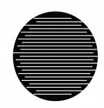
I have been searching the internet to see if I can find a way to calculate the inductance of parallel foil traces where there are opposing currents in adjacent traces as shown in the attached image. However, no luck in finding a not too complex way of doing this so now I post here and hope that one of you may know of a relatively simple way of calculating this.
Please note that the foil to be cut is not circular as in the image but a rectangle where the traces go from side to side on the short length of the rectangle. Thus adjacent traces almost have the same length. I hope this is somewhat clear ... 🙄
I'd much appreciate your insights on this 😉
Cheers,
Jesper
Attachments
It'easier than one may think. Have a look at "Self and mutual inductances of linear conductors" by Edward B. Rosa pp 338..341. It should be in the web for sure. Being of 1907 year it's absolutely free. Formula is too awkward post here and it needs correspondent drawing.
Thanks Alexberg - I will take a look at it (already found the text on the internet) ...
Cheers,
Jesper
Cheers,
Jesper
likely negligible for anything audio
FastHenry2 is free numerical solver code for Inductance/Mutual Inductance
awkward geometry description but fairly easy for your rectangular elements
Fast Field Solvers
FastHenry2 is free numerical solver code for Inductance/Mutual Inductance
awkward geometry description but fairly easy for your rectangular elements
Fast Field Solvers
Hi jcx,
Thank you also for your suggestion. I've taken a look at it, however, I would prefer to not have to get into a software program to find out of this - as I just need an approximate value.
Somewhat in line with your headline ...
Will keep it in mind, though, should reading alexberg's link not be accessible to me.
Cheers,
Jesper
@alexberg:
I've now read into the article you suggested and although the formula on pp. 338-341 is given for round wires (right?) it nevertheless is quite informative in terms of showing what happens in such a mesh of wires.
However, there is one question/thing that puzzles me in relation to calculating an inductance for a whole set of wires: As far as I can see the pp. 338-341 section of the paper mainly deals with the inductance of a single wire within the mesh of wires. It doesn't specify what the inductance of the whole mesh as such will be ... I could, as a way of finding the total inductance, add the inductance contributions of the individual wires but - and this probably is quite simple - since the current direction alternates between adjacent wires wouldn't the inductances of the "reverse" current wires have to be subtracted from the "reference" direction current wires? Or is there an easy way/a simple reasoning that may lead to an estimate of the total inductance in such a mesh - taking into account inductances of both the "reference" and "reverse" current wires?
I just need an approximate value.
@jcx: I decided to download FastHenry but not being a programmer (at all unfortunately) I reckon I could use some time getting familiarized with the program/debugging possible errors. So for a first round I will decide to let it be.
However, should you know of a similar program that is "visually based" I would very much like to hear about it.
Cheers & thanks,
Jesper
Jesper, in my opinion your drawing is that of a non-inductive resistor often used on PCBs. You can see from it that the direction of current switches between each conductor causing magnetic fields to cancel (from Fleming's left hand thumb rule).
Jesper, in my opinion your drawing is that of a non-inductive resistor often used on PCBs. You can see from it that the direction of current switches between each conductor causing magnetic fields to cancel (from Fleming's left hand thumb rule).
THIS
Its likley not exactly "non inductive" as the traces have a distance between them etc BUT for most part a layout as this should have inductance low enough to be of no importance in such use
Last edited:
What about measuring it instead using rather big capacitor to put frequency within the audio range? Or you may give exact dims and I can measure it using Al foil as a material. It would not take much time to cut 20 something slits by exacto knife.
Hi all,
Thanks for your feedbacks ... unless another diya member chips in with a specific formula for the wire "mesh" I probably will try to measure it.
Have a good evening ;-)
Jesper
Thanks for your feedbacks ... unless another diya member chips in with a specific formula for the wire "mesh" I probably will try to measure it.
Have a good evening ;-)
Jesper
- Status
- Not open for further replies.
- Home
- Loudspeakers
- Planars & Exotics
- Inductance of planar zig-zag foil pattern?