It's tough to confirm good accuracy if you don't have a reference inductor that has been measured on a calibrated meter (and is stable for physical dimensions, plus core characteristics if not an air-cored inductor), or you have another test technique that uses easier to obtain high accuracy calibration passive parts like 0.1% resistors and frequency.
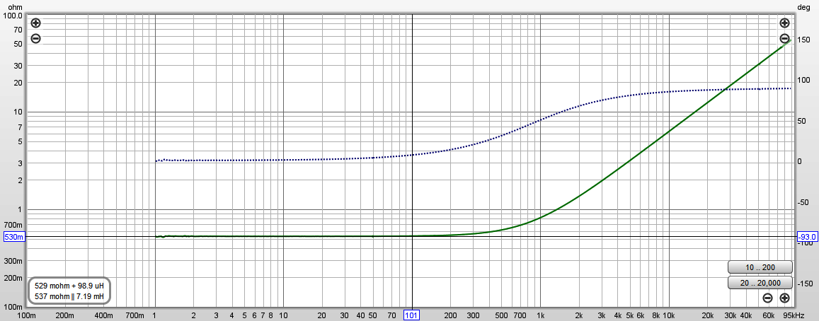
I luckily have two reference air-cored inductors of 10.5uH and 99uH (vintage 2nd grade Sullivan-Griffiths), so can confirm that the impedance measurement tool of REW (where I use a 0.05% resistor for a reference) adequately measures the value of the 99uH inductor (spot 98.9uH measurement at 100Hz shown in impedance plot below).
Similarly, the REW tool also confirms the same accuracy with the AC+DC measurement tool in the link:
https://www.dalmura.com.au/static/Choke%20measurement.pdf
Last edited:
electricboyo: Thanks for all your work on improving the LC100 meter! I have a question, though. Since (lifted from the Radio thread)
"Pressing the LC-100A “big C” button switches to a totally different measurement technique that relies on yet another internal reference capacitor. But this so-called “reference” capacitor is a 100uF electrolytic. In this case a timed charge-discharge is used to determine the uF. There is no L-C tank circuit for this mode. The LM393 forms a different type of oscillator (triangle wave R-C oscillator) for measuring "large C" (Hi.C button down). "Large C" is the only operational mode which uses the LM393."
Does the accuracy/tolerance of that 100uF cap make a difference in measuring large capacitors?
Does the accuracy/tolerance of that 100uF cap make a difference in measuring large capacitors?
Yes, that 100uF electrolytic on the LC100-A PC board is the reference for the “large C” range. It can easily be replaced or trimmed to provide a more accurate reference if desired.
I haven’t yet tried this with my LC100-A units. They are already accurate enough for my needs when it comes to measuring large uF values. Most electrolytic capacitors have a +/-20% uF value tolerance (or larger). My LC100-A units have < 3% error measuring large uF capacitors.
-EB
I’ve experimented with several inductors, both shielded and unshielded. The most important spec is the Q of the inductor at the operating frequency of the LC100-A oscillator circuit. This is roughly 200-500kHz. I haven’t noticed any difference between shielded vs. unshielded.My best guess from this is to use a 47uH high Q shielded inductor with a ferrite core. Anyone else come to a different conclusion?
Ferrite cores tend to have higher Q than powdered iron cores.
Typically the brightly-colored toroid inductors (yellow, green, blue, etc.) are powdered iron. Avoid those.
Actual ferrite cores are usually gray in color.
One person who contributed on the antique radio forum used a small ferrite rod antenna harvested from a broken transistor pocket radio. It worked great. The ferrite material used for AM radio antenna rods is generally selected for highest possible Q at 500-1500kHz. This is a good match for the LC100-A
When I evaluate inductors for the LC100-A I connect my x10 scope probe to the LC100-A test leads and observe the oscillation amplitude. The higher the better.
>1V P-P is desirable. Poor quality inductors will only give a 100-200mV P-P oscillation amplitude. That isn’t good enough.
Regarding uH value, I’ve tested inductors from 22uH up to 220uH. The LC100-A must be recalibrated each time the inductor is changed. However the actual uH of the inductor doesn’t seem to matter. The genuine MingHe LC100-A uses a 47uH inductor.
-EB
Last edited:
Hi All,
I have been reading through this interesting thread and I wonder if you might suggest a suitable measurement method for low inductance values?
I would need to measure inductances down to appr. 100 nH and the LC100-A I have gives ~ 660 nH for a 2% low resistance air core reference inductor specified at 530 nH.
The LC100A is an original MingHe with capacitors replaced and inductor replaced although not tested according to the description by electricboyo in the post above. I have, however, not replaced the comparator (LM311 I think it was).
Is there a simple & "economically accessible" way to measure this? I am attracted to the REW method described by trobbins & JohnPM (as I will be using something like REW shortly), however, I am unsure as to whether it will be precise at these low inductance values ... I need 1 - 2% precision.
I have also been considering using the LC100-A meter and then buy e.g. a couple of coilcraft precision inductors with values close to what I need and then extrapolate from the measurement values given by the LC100-A of these reference inductors. This obviously would be the easiest approach - if it can be considered sufficiently precise .. ??
I'd appreciate ideas or suggestions 😉
Cheers,
Jesper
Jesper, apart from the 99uH reference inductor in post #41, I also have a 10.5uH reference inductor which the REW based system measures as 10.5uH.
With the 99uH inductor the impedance starts to rise from low frequency 0.53 ohm at about 500Hz, and the phase from about 100Hz, and REW calculates 100uH at spot frequencies from 100Hz up (99uH at 20kHz when phase reaches 90 deg). The 10.5uH inductor impedance starts to rise from low frequency 5.3 ohm at about 20kHz, and the phase from about 5kHz, and REW calculates 10.5uH at spot frequencies from 100Hz up.
I'd anticipate similar accuracy down to at least 1uH, but without a reference you won't be able to tell no matter what method you use, so perhaps looking out for a 1% reference at 1uH may be your first hurdle to jump.
Question for diyAudio members who own a DE5000 inductance meter:Hi All,
I have been reading through this interesting thread and I wonder if you might suggest a suitable measurement method for low inductance values?
I would need to measure inductances down to appr. 100 nH and the LC100-A I have gives ~ 660 nH for a 2% low resistance air core reference inductor specified at 530 nH.
The LC100A is an original MingHe with capacitors replaced and inductor replaced although not tested according to the description by electricboyo in the post above. I have, however, not replaced the comparator (LM311 I think it was).
Is there a simple & "economically accessible" way to measure this? I am attracted to the REW method described by trobbins & JohnPM (as I will be using something like REW shortly), however, I am unsure as to whether it will be precise at these low inductance values ... I need 1 - 2% precision.
I'd appreciate ideas or suggestions 😉
Cheers,
Jesper
How accurate is the DE5000 for measuring inductances in the nH range?
I’ve been thinking about adding a DE5000 to my test gear array. But it’s a bit pricey in comparison to the LC100-A. At this point in time I’m still satisfied with the accuracy of the LC100-A. It has been “sufficiently accurate” for all of my projects so far.
Would the DE5000 work well for the project described by Jesper?
-EB
Very small inductors will not be reasonable at audio frequencies. 1 uH is 6 milliOhms at 1 KHz. Even with Kelvin connections adding 1 cm of lead will be a 20 % change. Those are best quantified ar much higher frequencies, preferable around the operating frequency.
An option would be a vector network analyzer. These used to cost what a house cost but there are now cheap ones like this NanoVNA-H 50KHz-900MHz Vector Antenna Network Analyzer VNA HF VHF UHF w/ Shell 889251529597 | eBay Do some homework but these may be the best choice. The price is unbelievable and I may get one even though I have an Agilent VNA on my bench. This video explains what you can do: NanoVNA - Measuring RLC Components - YouTube
An option would be a vector network analyzer. These used to cost what a house cost but there are now cheap ones like this NanoVNA-H 50KHz-900MHz Vector Antenna Network Analyzer VNA HF VHF UHF w/ Shell 889251529597 | eBay Do some homework but these may be the best choice. The price is unbelievable and I may get one even though I have an Agilent VNA on my bench. This video explains what you can do: NanoVNA - Measuring RLC Components - YouTube
...... a suitable measurement method for low inductance values? ..... I need 1 - 2% precision.....down to appr. 100 nH....... the LC100-A I have gives ~ 660 nH for a 2% low resistance air core reference inductor specified at 530 nH. The LC100A is an original MingHe with capacitors replaced and inductor replaced although not tested.
- Are your replacement capacitors 1% tolerance?
- Does your replacement inductor have high Q (>80)?
- Did you perform the complete calibration detailed by electricboyo AFTER replacements were installed?
I'll go you one better. I've attached a file I made for myself, gleaned from the Radio thread, and based mostly on the work of electricboyo. This delineates the calibration procedure and gives some insight to the workings of the LC-100A meter. This helped me tremendously and I hope it will help others.
Attachments
Hi again,
& thanks for your feedbacks & suggestions (and sorry about my slightly late reply - it has been some busy days).
@trobbins:
Would one of these work? All 1% yet different ohmic resistances ...
https://www.mouser.dk/Passive-Compo...-Inductors/_/N-wpczZ1yzvvqx?P=1z0wrifZ1z0wljo
@dotneck335: Thanks also for your feedback. In reply to this question of yours:
I have no idea about the inductor but the other capacitors are 1%. Would this inductor work:
RLB1314-470KL Bourns | Mouser Denmark
@1audio: Hi again - it's been a while - good to hear from you again ;-)
Hmmm ... I remember searching for a VNA a couple of years back - to my memory in relation to logic IC rise times or something like that ... However, it was indeed much more expensive back then ...
I have looked a bit into the suggestion of yours and it looks like a very interesting option. Will just ponder what possible uses it could have outside of inductor impedance measurements (e.g. measurement of impedances in HF capacitor decoupling networks?).
Cheers to all,
Jesper
& thanks for your feedbacks & suggestions (and sorry about my slightly late reply - it has been some busy days).
@trobbins:
so perhaps looking out for a 1% reference at 1uH may be your first hurdle to jump.
Would one of these work? All 1% yet different ohmic resistances ...
https://www.mouser.dk/Passive-Compo...-Inductors/_/N-wpczZ1yzvvqx?P=1z0wrifZ1z0wljo
@dotneck335: Thanks also for your feedback. In reply to this question of yours:
Does your replacement inductor have high Q (>80)?
I have no idea about the inductor but the other capacitors are 1%. Would this inductor work:
RLB1314-470KL Bourns | Mouser Denmark
@1audio: Hi again - it's been a while - good to hear from you again ;-)
An option would be a vector network analyzer.
Hmmm ... I remember searching for a VNA a couple of years back - to my memory in relation to logic IC rise times or something like that ... However, it was indeed much more expensive back then ...
I have looked a bit into the suggestion of yours and it looks like a very interesting option. Will just ponder what possible uses it could have outside of inductor impedance measurements (e.g. measurement of impedances in HF capacitor decoupling networks?).
Cheers to all,
Jesper
I just found this video on using a VNA on youtube should somebody else here be interested:
#359 How to properly use a NanoVNA V2 Vector Network Analyzer & Smith Chart (Tutorial) - YouTube
This one probably is even more relevant in terms of measuring inductances & capacitances - fascinating 🙂
nanoVNA - Measuring Inductors and Capacitors (Vers. 3) - YouTube
Jesper
#359 How to properly use a NanoVNA V2 Vector Network Analyzer & Smith Chart (Tutorial) - YouTube
This one probably is even more relevant in terms of measuring inductances & capacitances - fascinating 🙂
nanoVNA - Measuring Inductors and Capacitors (Vers. 3) - YouTube
Jesper
Last edited:
Jesper, 10uH is the smallest value of the reference standard I have.
The Murata datasheet doesn't have much info.
Perhaps take one step back and clarify what part you are trying to measure the inductance of, and why you need a measurement tolerance of 1%. It may also be worthwhile working through a resonance type test, using a capacitor with 1% tolerance, and a digital signal generator with better than 1% frequency tolerance (eg. I have a HP3325A that has sine output), and see what voltmeters you have with a wide frequency range (most good lab meters go to at least 100kHz, and others such as HP3400 go to 10MHz).
I just found this video on using a VNA on youtube should somebody else here be interested:
#359 How to properly use a NanoVNA V2 Vector Network Analyzer & Smith Chart (Tutorial) - YouTube....
This guy is hilarious; Andreas Spiess
#359 How to properly use a NanoVNA V2 Vector Network Analyzer & Smith Chart (Tutorial) - YouTube
It is a nice simple presentation of Smith chart & calibration of the analyzer.
...An option would be a vector network analyzer. These used to cost what a house cost but there are now cheap ones like this NanoVNA-H 50KHz-900MHz Vector Antenna Network Analyzer VNA HF VHF UHF w/ Shell 889251529597 | eBay Do some homework but these may be the best choice. The price is unbelievable...
😱 That price IS unbelievable. 😱
I mean, I believe it's the price but expletive deleted how can they do that?
I'm used to >$10k prices for VNAs, so thanks for the link
It should be possible to do audio amplifier loop gain tests with it.
Have you looked at this?
(Maybe there should be a new thread for this so as not to threadjack.)
Best wishes
David
"(Maybe there should be a new thread for this so as not to threadjack.)"
Yes, please. Thank you.
Yes, please. Thank you.
That is the very one I am going to use---it's 47uH (like the original MingHe), and its ultra-high Q of 90 should work very well.Would this inductor work:
RLB1314-470KL Bourns | Mouser Denmark
It's hard to make a meter better than its reference capacitor or inductor. Thus you need parts with as low a DF or as high a Q as possible at the frequencies of interest. Unfortunately, for inductors, that usually means a physically large part if you work at audio frequencies.
- Home
- Design & Build
- Equipment & Tools
- Inductance meter