Q10 has C8, but its mirror-image Q5 has no corresponding compensation capacitor?
The bias voltage generator Q13 has no bypass capacitor from collector to emitter?
The bias voltage generator Q13 has no bypass capacitor from collector to emitter?
Q10 has C8, but its mirror-image Q5 has no corresponding compensation capacitor?
Not needed, see Rod Elliot's article on this:
Compound vs Darlington
The bias voltage generator Q13 has no bypass capacitor from collector to emitter?
Yes, I've already added a 1uf cap in there, it's just not pictured in the schematic.
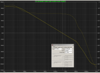
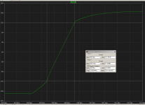
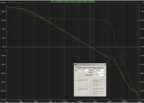
Out of curiosity I put your circuit in LTspice and the simulated results indicated no stability problems even without the C8. Transient response to square wave did show a gritty falling edge, but easily remedied with a 22-ohm VAS degeneration resistor. SR is good at about 54V/uS.
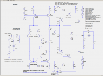
As shown in the schematic attached I did have an output zobel network and an input LPF. Output stage was biased at 55mA.
As shown in the schematic attached I did have an output zobel network and an input LPF. Output stage was biased at 55mA.
Attachments
Last edited:
Out of curiosity I put your circuit in LTspice and the simulated results indicated no stability even without the C8. Transient response to square wave did show a gritty falling edge, but easily remedied with a 22-ohm VAS degeneration resistor. SR is good at about 54V/uS.
As shown in the schematic attached I did have an output zobel network and an input LPF. Output stage was biased at 55mA.
Can you check with my exact circuit?
Can you check with my exact circuit?
I tried removing the input LPF, output zobel, output incudtor(short circuiting), and the power filters for front end circuit and there wasn't much change to the loop response. Only when the output is completely open circuit, i.e. neither the 8-ohm load nor the zobel is in place, is a "knee" seen on the loop gain curve.
Did you not have a zobel at the output when you did your simulation?
Attachments
- Status
- Not open for further replies.