Hi All,
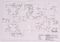
I've read a lot about so called sound improvements by increasing the idle voltage. The Destiny factory settings is 21.5mV. How is that value calculated? As I understand temperature control plays a major factor? But I've also read that the idle voltage is set below the ideal (Q-point?) voltage for the MOSFETs. Can anyone recommend safe upper limit for setting the idle voltage? I'm trying to improve the sound and favor softer over more detailed. Is 28mV too high? The heatsinks are quite warm but not too hot to the touch. I've attached the schematics for reference. The only modification I've made if any is replacing the HUF76639 MOSFETS with IRL2910.
Thanks for any help.
Best,
Gregory
Attachments
Last edited:
When you adjust the idle (bias) current with VR1 you measure the voltage at JP4 which gives the voltage across R28 a 0R33 ohms resistor. V=IR so 21.5mV drop gives about 64.5mA passing through R28 and that indicates the bias current through the output devices Q15, Q16, Q17 & Q18.
The Creek 5350SE is similar in many ways, and according to Welcome Secrets of Home Theater and High Fidelity
The Creek 5350SE is similar in many ways, and according to Welcome Secrets of Home Theater and High Fidelity
The 5350SE has four MOSFET output devices per channel, and is said to have minimal feedBack. A nominal bias (17 milliwatt) into class A classifies it as operating in a Class AB mode, and this is fairly typical of most class AB amps. There is usually just enough bias to keep the current flowing at zero signal. This is done to prevent the distortion created in a pure class B mode, when the signal passes from the positive to negative halves of the sine wave. Mike Creek explained that the bias point is not arbitrary, but chosen for optimal performance.
I see. Then I'm glad I stuck with 21.5mV. Thanks for the article🙂.
I measured the voltage across R44 (also .33 ohms) at 27mV on both channels. I'm not sure if this is expected but it sounds great so...
I measured the voltage across R44 (also .33 ohms) at 27mV on both channels. I'm not sure if this is expected but it sounds great so...
I see. Then I'm glad I stuck with 21.5mV. Thanks for the article🙂.
I measured the voltage across R44 (also .33 ohms) at 27mV on both channels. I'm not sure if this is expected but it sounds great so...
I also noticed R44 had a voltage of about 26/27mV so I guess it's OK! 🙂

The Creek 5350SE is indeed similar to the Destiny. Out of curiosity, I compared the Destiny schematic to the 5350SE mk2 v1.0 one which is available online and there seems little difference in the power amp section, although the Destiny uses surface mount transistors wherever poss. I have annotated the differences which I spotted.
The main differences between the amps appear to be in the power supply/delivery - I am not surprised that ensuring better power delivery should produce such sonic benefits.
The main differences between the amps appear to be in the power supply/delivery - I am not surprised that ensuring better power delivery should produce such sonic benefits.