hi Fellows
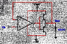
Below is the simplest way i think to add a stage to allow an op-amp circuit to supply more current to a load ie a speaker. However the main problem is that erm it has low input impedance and thus that's why the feedback. Also if say the op-amp output voltage range is from +13.5 volts to -13.5 volts and the maximum |Vbe| of the transistors is 0.85 volts at their maximum emitter current. Then the average power across the resistor would be 14.4 mW given the power = V*I and V and I has to be in rms. Could anyone correct me if this is wrong. And also would the output be the same for a sinewave input and a square wave input??
Below is the simplest way i think to add a stage to allow an op-amp circuit to supply more current to a load ie a speaker. However the main problem is that erm it has low input impedance and thus that's why the feedback. Also if say the op-amp output voltage range is from +13.5 volts to -13.5 volts and the maximum |Vbe| of the transistors is 0.85 volts at their maximum emitter current. Then the average power across the resistor would be 14.4 mW given the power = V*I and V and I has to be in rms. Could anyone correct me if this is wrong. And also would the output be the same for a sinewave input and a square wave input??
Attachments
I assume that you want some hifi from this circuit so you will need some bias circuitry for the output transistors. Depending on opamp and the output stage you will get 11-13 volts peak.
11^2/(100*2) = 0,605 W
13^2/(100*2) = 0,845 W
11^2/(100*2) = 0,605 W
13^2/(100*2) = 0,845 W
Hi peranders,
Judging from your calculations, that means if i measure the op-amp output range to be 13.5 then my calculations would be
13.5^2/(100*2) = 0.911W
Judging from your calculations, that means if i measure the op-amp output range to be 13.5 then my calculations would be
13.5^2/(100*2) = 0.911W
You probably will not get 13.5 volts out of that, unless the op-amp can go very close to the rails.
Jocko
Jocko
Correct, Edo, but you don't have be so accurate if you shall use the output for audio. Think in decibells. The difference will be 3-4 decibells only, 119-123 dB (in your ears) maybe....
Calculate for at least 10 V peak out. This will you get for sure.
Calculate for at least 10 V peak out. This will you get for sure.
Hmm ok, but there is this question in my head right now. How do we find the power that is dissipated in each transistor??? And usually our input sound wave is a sine wave right. What happens if the input is a square wave??? Would it make any differents to the output and calculations???
Edo,
A perfect sinewave will product exactly one half the power of a perfect squarewave into a resistive load.
As Peranders says the average power output for a sinewave is Vpeak^2/(2*R). For a squarewave it will be Vpeak^2/R.
Working out the power dissipated by each transistor is more complicated. The easiest case is for a squarewave where you multiply the tarnsistor current by the voltage drop across it. So if the power supply voltage is Vpsu then when a transistor is ON its power will be (Vpsu-Vpeak)*Vpeak/R. Since each transistor is on only half the time its average power is half of this.
For a sinewave it is more complicated and the maximum transistor power dissipation does not occur at maximum voltage output. Peranders and I discuss this in another thread. If your transistors are biased just into class AB (they are just into conduction when the output voltage is zero) each of your two transistors must be able to dissipate at least Vpsu^2/(10*R).
Hi TraderBam,
Hmm finding power indeed sounds pretty complex. Do you know of any web site that has the formula so as i can take alook at it to be more familiar with it.
Hmm finding power indeed sounds pretty complex. Do you know of any web site that has the formula so as i can take alook at it to be more familiar with it.
power dissipation
As a rule of thumb you can say that the maximum heat dissipation of the transistors is reached at 2/3 of the output power.If they don't get too hot at this point, they'll stand continuous operation under all normal conditions.
Arne
As a rule of thumb you can say that the maximum heat dissipation of the transistors is reached at 2/3 of the output power.If they don't get too hot at this point, they'll stand continuous operation under all normal conditions.
Arne
Correct
Max dissipation occurs at 2/3 of maximum voltage swing.
I would concentrate more on how much to bias them. The hotter, the better. Assuming that the op-amp will still drive them at that current level.
Jocko
Max dissipation occurs at 2/3 of maximum voltage swing.
I would concentrate more on how much to bias them. The hotter, the better. Assuming that the op-amp will still drive them at that current level.
Jocko
Hi Jacko,
Could I know why is it the hotter the better??? I thought if it get too hot then thermal runaway sets in and your device would fail to work???
Could I know why is it the hotter the better??? I thought if it get too hot then thermal runaway sets in and your device would fail to work???
Hotter means more bias
All that assumes you have a big enough heat sink. Which should not be hard if you only need to drive 100 ohms.
Jocko
All that assumes you have a big enough heat sink. Which should not be hard if you only need to drive 100 ohms.
Jocko
Re: power dissipation
I have a vauge memory of that it isn't 2/3 but only 1/3. Too lazy to calculate this. I'll get back with more facts or someone maybe can confirm this?
yeti said:As a rule of thumb you can say that the maximum heat dissipation of the transistors is reached at 2/3 of the output power.If they don't get too hot at this point, they'll stand continuous operation under all normal conditions.
I have a vauge memory of that it isn't 2/3 but only 1/3. Too lazy to calculate this. I'll get back with more facts or someone maybe can confirm this?
Simple circuit
Hi Edo,
Your circuit reminds me of the first circuit I ever built with a OP01 and two transistors. Precision Power Booster from the datasheet of the OPO1, 1984 PMI databook. It had the emittors connected to the power rails though. It did not sound bad! Your circuit suffers from crossover distortion. The PMI circuit had not as the bases were driven of the sensed powersupplies of the IC.
Imediately thereafter I built the circuit as in the Walt Jung book; Audio IC Op-Amp Applications, universal line driver. It looks just like your circuit but with a LED between the bases of the transistors to provide some bias at low signal conditions. To make a POWER amp of it I believe you will need much more drive (amperes) to the output transistors. Or start with Darlington connected outputtransistors etc. etc. ....😉
I thought Max Power Waste was attraderbam said:max power at (2/pi)*Vpsu
(sqr(2))/2 x Vb = 0.707 x Voltage. For sine-waves.
I am probably wrong. 😕 😎
Wow lots of answer but erm which one is the correct one regarding the sine wave???
Elso Kwak The circuit which i showed has cross over distortion err because it's a class B amp i think. Do you have any idea what does the feedback do in this case. It doesn't cure cross over because to do that i might need to put two diode over it. Erm do you know how to calculate the power in this circuit??
Ed
Hi Edo,Edo said:Elso Kwak The circuit which i showed has cross over distortion err because it's a class B amp i think. Do you have any idea what does the feedback do in this case. It doesn't cure cross over because to do that i might need to put two diode over it. Erm do you know how to calculate the power in this circuit??
Ed
Your answer reminds me of a mistake I made by forgetting to bias the outputstage of my just built lineamp. Sound was perfect except at very low volume, when the music fades away, all of the sudden it was silence!
I scratched my head but did not have a clue. At last I took my scope and looked at the outputwaveform (sine). It looked like classic crossover distortion and I quickly found the forgotten solder joint.
In your case at least two diodes should be connected between the bases of the transistors and resistors to the supplies.😉 To prevent thermal runaway emittor resistors (resistors in series with the emittors of the outputtransistors ) might be usefull. Typical value 10 to 30 Ohm. Some power is sacrified and burned up in these resistors.
I do no SPICE, just like Jocko😉, just measure the maximum undistorted voltage ouput and calculate VxV/R. In your case R= 100
😉
- Status
- Not open for further replies.
- Home
- Amplifiers
- Solid State
- Increasing current