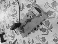
Installed replacement 1st condenser 100uf appliance run capacitor (polypropylene, non-electrolytic)
But hum comes bigger, why?
Run capacitor has sealed pigtail leads eight inches long untwisted, soldered into original capacitor's pcb landings.
How can high tension dc fed by bridge rectifier introduce bigger hum?
Can proximity wiring affect 8" untwisted run capacitor, either influx into ht or efflux out ht into susceptible wiring?
Or could it be the swapout to one meg audio taper of gain and level pots?
the bigger the capacitor, the bigger the currents through the mains transformer. This indicates me that a magnetic coupling between the mains transformer and (likely) the output transformers is inducing hum. It is also possible that the wring between rectifier and 1st capacitor is part f the ground plane of your circuit. A photo or exact layout would be helpful
rescind appliance run capacitor install
Rescinded appliance run capacitor install.
It is not the problem of hum invite.
It was 96.4 but factory 88.2 is accurate enough per schematic call.
The meg pots are amplifying way too much.
So I Rescinded both, instead using twenty kilo linear for level.
That reduced hum, as the preamp tube does not trump dc heat.
I'm wondering how much gain resulted by those meg pots? Did not get chance to plug in guitar, amp runaway in looped feedback without input, meaning gain is out of control, likely in the burrbrown2134.
 So this is a guitar amp, looks like I am moving it again. Guitar amp threads belong in Instruments & Amplifiers.
You might get a little help over there, but changing the gain control pots is probably not the right thing to do.
pot does manipulate performance
By changing pot temperament, the upstream signal can be throttled more pronounce'fully.
It's no different than changing guitar pot values on a particular signal generator (pup).
Realize pot can be viewed as an obstruction to signal growth. If we constipate the signal chain with a pot meg ohm, upstream signal will "bloat", meaning amplitude grows. The reciprocal would be to "unbloat" the upstream signal, say by pot tenth meg ohm, whereby signal can thrive into earth fullspeed, of which particular frequencies get trashed more readily and with purpose too for signature appeal remainder signal unearthed.
You might get a little help over there, but changing the gain control pots is probably not the right thing to do.
By changing pot temperament, the upstream signal can be throttled more pronounce'fully.
It's no different than changing guitar pot values on a particular signal generator (pup).
Realize pot can be viewed as an obstruction to signal growth. If we constipate the signal chain with a pot meg ohm, upstream signal will "bloat", meaning amplitude grows. The reciprocal would be to "unbloat" the upstream signal, say by pot tenth meg ohm, whereby signal can thrive into earth fullspeed, of which particular frequencies get trashed more readily and with purpose too for signature appeal remainder signal unearthed.
About changing the cap in the PSU : the legs of the cap should be virtually non-existent, so eight inches is an astronomic lenght 🙄
Come on, hewo, you've been around long enough, tell everyone it is a CRATE VC508, unless it is something else, and put up a schematic so everyone can see what you are talking about:
http://bmamps.com/Schematics/crate/Crate_VC-508_(07S251)_Schematic.pdf
You surmise changing the cap increased the hum, then only as a parting thought you mention changing pot values. What else did you change? Not sure what the new cap was going to do, but as DC it won't radiate much from its wires, or pick up anything. In post #3 you add you apparently changed the op amps. Anything else?
What does this refer to?
Pot values changed? Oh dear... Look at the first stage, gain pot P3 is 250k, and combines with 2.2k R5, that ration sets the gain of the op amp. By quadrupling that value you upset the designed gain of the stage. And later, the volume control P1 is part of a voltage divider comprising R6, R11, and the tone circuits, plus P1. Looking just at R6 and P1, they form a 10/1 voltage reduction in signal level leaving the tone controls. If you made p1 a 1 meg then you have reversed it to a 1/10 voltage reduction of signal.
So looking at the circuit, the output from P1 is meant to be a line level signal, about 1 volt. The signal is shown as 30v p-p under test conditions at the preceding plate, so with a 1 meg pot, instead of about a volt all the way up, your signal level would be a lot closer to that 30v level. That would seriously overdrive anything in the line out jack, as well as hugely overdrive the following grid. Note the plate of that following triode only expects about 10v p-p, but if you start with more than that at the grid, it won't be happy.
So it is vastly different from changing the pots on a guitar. They affect impedance, but not overall signal levels or gain.
So what you did was increase gain in the first stage, but also increased signal level at the master volume. I don't doubt the amp is not stable.
http://bmamps.com/Schematics/crate/Crate_VC-508_(07S251)_Schematic.pdf
You surmise changing the cap increased the hum, then only as a parting thought you mention changing pot values. What else did you change? Not sure what the new cap was going to do, but as DC it won't radiate much from its wires, or pick up anything. In post #3 you add you apparently changed the op amps. Anything else?
It was 96.4 but factory 88.2 is accurate enough per schematic call.
What does this refer to?
Pot values changed? Oh dear... Look at the first stage, gain pot P3 is 250k, and combines with 2.2k R5, that ration sets the gain of the op amp. By quadrupling that value you upset the designed gain of the stage. And later, the volume control P1 is part of a voltage divider comprising R6, R11, and the tone circuits, plus P1. Looking just at R6 and P1, they form a 10/1 voltage reduction in signal level leaving the tone controls. If you made p1 a 1 meg then you have reversed it to a 1/10 voltage reduction of signal.
So looking at the circuit, the output from P1 is meant to be a line level signal, about 1 volt. The signal is shown as 30v p-p under test conditions at the preceding plate, so with a 1 meg pot, instead of about a volt all the way up, your signal level would be a lot closer to that 30v level. That would seriously overdrive anything in the line out jack, as well as hugely overdrive the following grid. Note the plate of that following triode only expects about 10v p-p, but if you start with more than that at the grid, it won't be happy.
So it is vastly different from changing the pots on a guitar. They affect impedance, but not overall signal levels or gain.
So what you did was increase gain in the first stage, but also increased signal level at the master volume. I don't doubt the amp is not stable.
Even with Google Translate, I can not understand what you are saying...By changing pot temperament, the upstream signal can be throttled more pronounce'fully.
It's no different than changing guitar pot values on a particular signal generator (pup).
Realize pot can be viewed as an obstruction to signal growth. If we constipate the signal chain with a pot meg ohm, upstream signal will "bloat", meaning amplitude grows. The reciprocal would be to "unbloat" the upstream signal, say by pot tenth meg ohm, whereby signal can thrive into earth fullspeed, of which particular frequencies get trashed more readily and with purpose too for signature appeal remainder signal unearthed.

vc508 absurd gain actually okay
While the vc508 had those incredibly high signal, the speaker voiced incredibly maybe because the ot is an over rated edcor at 18va?
Anyhow dials had to be babied to stay away from overheating el84.
I restored the factory gain pot but settled on volume pot of twenty instead of ten kilo ohms.
The appliance running cap 96.4uf is well worth it! The eight inch leads are not deleterious to creation hum, how do I know, scope. So I will recap all powering electrolytics on tubes with such appliance running caps, they're significant breathability, airy.
Also experimenting with inductor on tone wiper earth dump, about 1k, 42gauge windings over iron core slug. Looks like highs get reflected back upstream instead of annihilated. I also will experiment tone pot change, go bigger, like meg linear. Trick is to tailor ranging of it for useful signatures (not dark!)
I visited a long time friend musician yesterday to bring back his amp that's been revived from the dead.
We were talking and it became a bit psychedelic...
He asked me if I smoked something on the way? Maybe he did...
(I'm a non smoker btw...)
Our talking was a bit like what's going on here; Very hard to understand or to follow.
But hey, I'm from this side of the water.
I hope some one can understand you when you give more details about what you've done. Enzo can see through your writing it seems.
Tarzan, I catch his gist, but I also find it very hard to understand. I prefer to use clear statements.
vc508 tone wiper inductor
Yes, inductor works, the bass can slide thru but higher frequencies bounce back upstream.
What's needed is a variable cap for c9 and 12.
Inductor loses energies selectively but overall loses less energies were it absent.
It has selectively retained highs while discarding lows, it is a tuned bandpass, right?
The volume pot now twenty kilo ohms rides much better, permitting access into the optimal sounding strength.
forgotten disclosure additional alterations vc508
Both ecc83 cathode resistors changed to 820 ohms each metalfilm 1% 1/2 watt.
Appended paralleled run caps polypropylene foil, 224 on 10uf 1st preamp stage ecc83, 684 on 10uf 2nd preamp stage ecc83, 334 on el84's 100uf.
Snubbed power switch paralleled 224 run cap polypropylene foil (should be 502 as 224 creates distress sigh speaker gasp on power kill), purpose of snubber cap is to kill switch spike on power kill.
Inserted series, to tone wiper, 1k ohm 42gauge wire inductor to earth, to preferentially annihilate bass frequencies unwanted esp with larger gain and larger volume settings. This required sleeving the wiper's pcb well with teflon to isolate wiper pigtail protruding soldering landing, thus exposing the pigtail and pcb landing independently isolated for inductor insertion.
increased power resistor wattage handling, r20/r18 five watts, r17 ten watts.
P1 increased to 20k linear, but gain and tone remain factory schematic.
HT rectifiers changed to those ultra fast type and greater handling current.
Tone circuit hipass c9 changed to 221 hiQ type disc, c12 tiedown continuity reduced to 101 hiQ type disc.
Both dc blocking c8/c14 upgraded polypropylene foil (bulkier because not metalized film) sounds much much sweeter.
Edcor ot 18va 8ohm out, 5k input impedance, but paper speaker is 16 impedance, cleaner output but reduction power transferred.
Welded toe extension on one side of el84 brace, because slm design errored in brace alignment bolting holes.
220vac axial fan soundshort mounted (sponge mounts) to chassis impinging winds direct blast onto pt close proximity 1/2" separation.
Spare tube clamp affixed to el84 brace.
Abandoned incandescent lamp parasitic rob energies heaters, by inserting rectified heater energy into quad seagull micro led series coupled, totalized current drawn fractional milliamp!
Copper foiled backboard panel of electronic tray, as it is not made of metal, and emi can infiltrate thru pressed board.
Come on, hewo, you've been around long enough, tell everyone it is a KUSTOM TUBE 12CRATE VC508, unless it is something else, and put up a schematic so everyone can see what you are talking about:
http://bmamps.com/Schematics/crate/Crate_VC-508_(07S251)_Schematic.pdf
You surmise changing the cap increased the hum, then only as a parting thought you mention changing pot values. What else did you change? Not sure what the new cap was going to do, but as DC it won't radiate much from its wires, or pick up anything. In post #3 you add you apparently changed the op amps. Anything else?
What does this refer to?
Pot values changed? Oh dear... Look at the first stage, gain pot P3 is 250k, and combines with 2.2k R5, that ration sets the gain of the op amp. By quadrupling that value you upset the designed gain of the stage. And later, the volume control P1 is part of a voltage divider comprising R6, R11, and the tone circuits, plus P1. Looking just at R6 and P1, they form a 10/1 voltage reduction in signal level leaving the tone controls. If you made p1 a 1 meg then you have reversed it to a 1/10 voltage reduction of signal.
So looking at the circuit, the output from P1 is meant to be a line level signal, about 1 volt. The signal is shown as 30v p-p under test conditions at the preceding plate, so with a 1 meg pot, instead of about a volt all the way up, your signal level would be a lot closer to that 30v level. That would seriously overdrive anything in the line out jack, as well as hugely overdrive the following grid. Note the plate of that following triode only expects about 10v p-p, but if you start with more than that at the grid, it won't be happy.
So it is vastly different from changing the pots on a guitar. They affect impedance, but not overall signal levels or gain.
So what you did was increase gain in the first stage, but also increased signal level at the master volume. I don't doubt the amp is not stable.
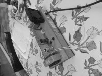
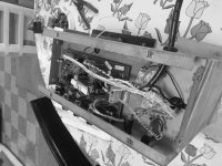
Sounds and looks to me like you somehow murdered a cheap champ knockoff. All the while making it sound mystical and psychedelic, like it it made of mojo and patchouli and cinnamon. The b&w photos add a rustic touch to a topic so well descriptionated. The transmutation of sand based to tubular character in the driving force of the music factorizer is astonishingly astounding. Wow.
I wish you great success with your project, but for the life of me, I can't figure out what you are trying to achieve.
I wish you great success with your project, but for the life of me, I can't figure out what you are trying to achieve.
Last edited:
Achieve the proper spectrum of luscious "edge" , that "wet" even ordered harmonic coloration of frequencies and proportions restrained
- Status
- Not open for further replies.
- Home
- Live Sound
- Instruments and Amps
- Increased hum from changing 1st condenser vc508 schematic