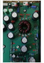
I want to increase rail voltage by 4 to 5 volts... I have added picture of the PWM IC.
Current rail voltage is +-28v, capacitors are 35v. So I want to increase voltage to 31v to 33v by changing the duty cycle of TL494
Amplifier is ADS p440

Current rail voltage is +-28v, capacitors are 35v. So I want to increase voltage to 31v to 33v by changing the duty cycle of TL494
Amplifier is ADS p440
Does it have a reduced duty cycle as of now?
If so, DCV on pins 1, 2, 15 and 16? Black probe on pin 7.
If so, DCV on pins 1, 2, 15 and 16? Black probe on pin 7.
Isn't the rail voltage set by the ratio of the primary to secondary windings at the transformer ??!?!

The PWM controller for car audio amp power converter could be designed in three ways:
1) without any regulation (why not, it's cheap))
2) with output limit for abnormal power (>15V),
3) with regulation in working range (e.g.11V-15V).
For cases 1) and 2) it runs on maximum duty cycle when input power is within normal range and rails voltage are defined by transformer.
Only the last case allows you to increase rails voltage by changing the voltage sense divider.
You can figure out your case by using lab supply, change input power from 10V to 15V and check if (and how) rails voltage changes.
@Perry Babin pin 1 2 are 0v, pin 15 16 4.65v
@Maserito rail voltage at 11.85v is 21.35v, at 15v its 27.5v
@Maserito rail voltage at 11.85v is 21.35v, at 15v its 27.5v
It's not regulated to where a small mod would give you more rail voltage.
Having the same exact voltage on both inputs of a single error amplifier isn't likely to be right. What resistance do you read from pin 1-2? From pin 15-16?
Having the same exact voltage on both inputs of a single error amplifier isn't likely to be right. What resistance do you read from pin 1-2? From pin 15-16?
It's a great chip, PWM voltage regulation, overvoltage and amp output problems should you wish to add.
Looks like case 2 to me, with error amp.2 not used at all, turned off by large voltage between pins 15 and 16.
Then measure the rails voltage, it must be higher than before.
If it does not go over 27.5V check voltage on pins 1 and 2:
In fact you need to add 2 turns as secondary winding is center tapped for sure. 1 turn to be added to each half of the secondary winding.What if I add 1 more turn to the toroidal transformer
Then measure the rails voltage, it must be higher than before.
If it does not go over 27.5V check voltage on pins 1 and 2:
- if there are few mV between 1 and 2 the PWM regulation is active and you have to change voltage divider(s) to increase output;
- if pin 2 is >10mV more positive than pin 1 the error amp.1 is off (max duty cycle) and you need to re-check pins 15 and 16 - as error amp.2 can reduce duty cycle too.
@Maserito Please guide here. Which wires of the torodoil transformer should I add turns and how much. It has red and green wires. My guess is green but I dont want to experiment.
Also I dont think this will be an issue because this amp is able to run until 16v which will increase rail vaoltage to 30v. While in automotive conditions the input is not even 14v
I try but you have to be very careful not to damage the working amp, you do this at your own risk)
Do not proceed further if something differs from the instruction unless you understand how it works.
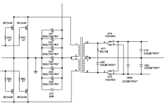
1. Your power converter is similar to the diagram below (classic push-pull), but rectifiers (D74, D75) are different. I believe positive rail is on VD1-2 center pin, negative - VD3-4 center pin.
2. Please check VT1 and VT2 types - these should be NPN and PNP bipolar transistors respectively.
3. Desolder the transformer, check windings - should be 1-2, 3-4, 5-6, 7-8.
4. Ensure PCB holes 6 and 7 is solid ground, 2 and 3 are connected to input power +12V.
5. Check that 1 is connected to Q1 and Q2 drains (center pin), 4 is connected to Q3 and Q4 drains.
6. Check diodes VD1-2 and VD3-4 - should be dual diodes with common cathode and common anode (center pin) respectively.
7. Check that 5 and 8 are connected to VD1-2 and VD3-4 side pins.
8. Transformer! Add 1 turn to 5 and 1 turn to 8; mind wire gauge and isolation.
9. Solder the transformer back, power from +12V (not +15V) and check rails voltage.
10. Low voltage stabilisers VT1, VT2 will be stressed more after that mod.
Do not proceed further if something differs from the instruction unless you understand how it works.
1. Your power converter is similar to the diagram below (classic push-pull), but rectifiers (D74, D75) are different. I believe positive rail is on VD1-2 center pin, negative - VD3-4 center pin.
2. Please check VT1 and VT2 types - these should be NPN and PNP bipolar transistors respectively.
3. Desolder the transformer, check windings - should be 1-2, 3-4, 5-6, 7-8.
4. Ensure PCB holes 6 and 7 is solid ground, 2 and 3 are connected to input power +12V.
5. Check that 1 is connected to Q1 and Q2 drains (center pin), 4 is connected to Q3 and Q4 drains.
6. Check diodes VD1-2 and VD3-4 - should be dual diodes with common cathode and common anode (center pin) respectively.
7. Check that 5 and 8 are connected to VD1-2 and VD3-4 side pins.
8. Transformer! Add 1 turn to 5 and 1 turn to 8; mind wire gauge and isolation.
9. Solder the transformer back, power from +12V (not +15V) and check rails voltage.
10. Low voltage stabilisers VT1, VT2 will be stressed more after that mod.
Attachments
Last edited:
- Home
- General Interest
- Car Audio
- Increase rail voltage by 4 volts(TL494)