I am fine thanks, I shall try and find one of those bulbs. what voltage should the trans be putting out to the bridge?OUCH!!!!!!
There is some GROSS mismatch there, VERY DANGEROUS!!!
Such a big capacitor,can and will explode like a grenade, straight in your face.
You were lucky you didn´t get hurt.
At least I HOPE you didn´t. 😱
Clearly you connected it wrong: 70VAC into a bridge (which means rectified 100V peak) into a single 63V cap.
1) do not plug anything into Mains until this mystery is solved.
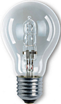
2) build a current limiting bulb setup,with a 40 to 60W tungsten filament bulb as limiter.
Real glowing wire inside a bulb type, no LED, CFL, etc.
You can still buy them as "high efficiency ones", an olive sized quartz halogen bulb inside a larger old style glass one.
Please draw what you built, plus a picture.
Comparing your picture to the Service Data manual:The tx is out of the amp at the moment but this is it roughly connected up, I did connect a cap 22000uh 63v briefly and the meter showed 95v before the cap blew
it looks like you are correctly connected for a 240v AC primary, and measuring across the bridge rectifier output. In which case, this should be developing ~100v peak half-wave rectified at the measurement point. Without any smoothing capacitors, this may well measure as ~100v/sqrt(2) = 71v DC, so I'm not surprised at your reading.
As there is no DC load, connect any 63v minimum capacitors from Vout+ and Vout- to the ground point at 6A/6B/7A/7B, these will 'hold' the peak voltage and you should then measure 100v DC at your measurement points (or 50v DC from either to ground).
(Your 'brief' experiment with an under-rated capacitor supports this analysis)
Last edited:

You connected 22000uF (1) how? and (2) why? You need to stop randomly experimenting, especially as you don't appear to know what you're doing.
Thanks, but we need better readability 🙂
And more data.
1) please somebody post the Service Manual PDF so I can enlarge images and read them properly.
2) I can barely read secondaries in post #22, even opening image in another tab, I see "labels" such as "5A", etc, which mean little or nothing to me.
3) the supplied schematic is unreadable, and lacks some voltages (specially PT AC voltages)

4) the transformer shown is unreadable,and where the h*ck do those wires go?
Including meter wires, which disappear at image edge towards an unknown destination.
And we don´t see the diodes,the capacitor(s), a mess.
Can´t read the meter scales,only a big 69 which by itself means nothing.
All this said with best intentions: NO DATA NO ANSWERS POSSIBLE.

5) the original (poor quality) schematic is fine, but does not show the transformer, no AC voltages, etc.

And more data.
1) please somebody post the Service Manual PDF so I can enlarge images and read them properly.
2) I can barely read secondaries in post #22, even opening image in another tab, I see "labels" such as "5A", etc, which mean little or nothing to me.
3) the supplied schematic is unreadable, and lacks some voltages (specially PT AC voltages)
4) the transformer shown is unreadable,and where the h*ck do those wires go?
Including meter wires, which disappear at image edge towards an unknown destination.
And we don´t see the diodes,the capacitor(s), a mess.
Can´t read the meter scales,only a big 69 which by itself means nothing.
All this said with best intentions: NO DATA NO ANSWERS POSSIBLE.
5) the original (poor quality) schematic is fine, but does not show the transformer, no AC voltages, etc.
By now I am not worried by primaries, any gross error there (as in connecting 120V wiring to 240V mains) would instantly blow mains fuse, and for the fraction of a second it takes, lights would dim, transformer buzz horribly,etc. ; nothing like that is being described.it looks like you are correctly connected for a 240v AC primary,
Bridge End-to-end?and measuring across the bridge rectifier output. In which case, this should be developing ~100v peak half-wave rectified at the measurement point.
Agree.
But capacitors do NOT connect end to end (what´s apparently happening here); we have two of them, each must go from proper rail to ground, which is half the end to end peak voltage.
There is a gross wiring error here, but we need a hand drawn schematic plus a picture to debug that.
Or homemade hand grenades will keep going off.
I think AC and DC are being treated as one and the same here ....... which of course they are not.Without any smoothing capacitors, this may well measure as ~100v/sqrt(2) = 71v DC, so I'm not surprised at your reading.
I suggest every time Voltage is mentioned, it be accompanied by AC or DC labels, no "assuming" acceptable.
That.As there is no DC load, connect any 63v minimum capacitors from Vout+ and Vout- to the ground point at 6A/6B/7A/7B, these will 'hold' the peak voltage and you should then measure 100v DC at your measurement points (or 50v DC from either to ground).
No underrated capacitor here but a wrong connected one.(Your 'brief' experiment with an under-rated capacitor supports this analysis)
IF connected as per original schematic, 63V capacitors smoothing 50V rails are perfectly fine.
We NEED OP drawings and pictures showing actual "experimental" connection.
Just saying "it is like in the schematic" does not hold, we need the actual wiring.
By now I am not worried by primaries, any gross error there (as in connecting 120V wiring to 240V mains) would instantly blow mains fuse, and for the fraction of a second it takes, lights would dim, transformer buzz horribly,etc. ; nothing like that is being described.
I was only pointing out that the primary wiring in the OP's picture matched the '240v' case in the service data, so as you say, no gross error:
Bridge End-to-end?
Agree.
But capacitors do NOT connect end to end (what´s apparently happening here); we have two of them, each must go from proper rail to ground, which is half the end to end peak voltage.
There is a gross wiring error here, but we need a hand drawn schematic plus a picture to debug that.
Or homemade hand grenades will keep going off.
Certainly not in an actual 405, but the OP had just the transformer and bridge rectifier on the bench, then appears to have applied a capacitor across the rails. As such, I don't see evidence of a gross wiring error.
I think AC and DC are being treated as one and the same here ....... which of course they are not.
No not at all. The bridge will be rectifying the AC, but without peak storage capacitors, it will look like the middle plot in this picture (I apologise I mistakenly called it half-wave rectified; it is of course full-wave). The peak value is 100v, but the measured DC (RMS value) will be 71v.
Adding smoothing capacitor(s) will give the lower plot, and a measured DC of ~100v.
These all fit well with the OP's measurements, so to me it appears to be functioning as expected.
No underrated capacitor here but a wrong connected one.
IF connected as per original schematic, 63V capacitors smoothing 50V rails are perfectly fine.
In the OP case, I'm infering a 63v capacitor was connected across the rails, with a peak voltage of 100v, so potentially sub-optimal to it's own and anyone nearby's health!
Last edited:
Put it all back together, and connect the boards, and measure the DC voltages at the PSU capacitors from the red wire to the green wire, and from the green wire to the black wire. You should get about 50VDC in both cases.
I suggest you have never done this correctly, and that there is no actual problem to solve.
I suggest you have never done this correctly, and that there is no actual problem to solve.
Well, doing things wrong IS a problem to solve, don´t you think?
Also not referring to Quad original wiring, but the current one which explodes capacitors like grenades.
In any case, we are like moths flying around a candle until the OP improves data.
Also not referring to Quad original wiring, but the current one which explodes capacitors like grenades.
In any case, we are like moths flying around a candle until the OP improves data.
Whatever the thinking or process or hookup was that led to exploding a $50 capacitor is certainly a problem to solve, but there is no evidence here that there was ever anything wrong with this 405.
Since nobody posted a full manual with the various options, here's a link to the 405 model service manual and the relevant schematic page. There are also other 405 manuals and other sites that you may need to sign up for, but for me at least, it was free, fast and simple. The original schematics were poorly or faintly reproduced anyway so don't expect PDF document quality images.
https://www.manualslib.com/manual/1451125/Quad-Electroacoustics-Quad-405.html#manual Try the page 15 schematic for a closer look at PSU wiring for most models and options.
https://www.manualslib.com/manual/1451125/Quad-Electroacoustics-Quad-405.html#manual Try the page 15 schematic for a closer look at PSU wiring for most models and options.
I have attached a pic to show how I have connected the tx up on the bench, not pretty but it illustrates the method. I would add that I have not powered this setup again after the last cap blew also I have not connected to a board for similar reasons. this is connected according to the diagram at https://www.dadaelectronics.eu/uplo...05-and-405-2-Upgrade-Revision-Manual-V2.0.pdf page 12

That looks correct. And +50v from red test lead to earth, -50v from black test lead to earth?. If so, then all seems as it should.
ok, I shall put it all back in the case and check again thanksThat looks correct. And +50v from red test lead to earth, -50v from black test lead to earth?. If so, then all seems as it should.
green/yellow? which one in particular? the trans was wired for 240v when I got itThe green/white wire on the secondary doesn't look correct. Did you do that?
Not so fast.ok, I shall put it all back in the case and check again thanks
FIRST answer:
To which I would add out of abundance of precaution (and because that is the capacitor blowing voltage):richb said:
That looks correct. And +50v from red test lead to earth, -50v from black test lead to earth?. If so, then all seems as it should.
measure across each capacitor legs (or those nifty screw terminal blocks clamped to each one) and post results.
Special negative points for having use RED as "ground".
Feel free to use any colour for ground except Red or Black which have very specific meanings.
That's the one. It looks to be connected between either two points that shouldn't be connected or else two points that are already connected. This is not as per factory. Someone has added this.green/yellow?
Irrelevant. I am talking about the secondary.the trans was wired for 240v when I got it
OK, it's hard to see from your photo, but if the green/yellow wire is connecting the centre two posts of the secondaries it is correct. But it isn't an original Quad wire, which would have been yellow like the others. Someone has been doing strange things to this transformer, or at least pointless things.
Was it you?
Was it you?
As ejp said, if it follows the highlighted wire from the manual posted above (which it potentially does), it's correct:

- Home
- Amplifiers
- Solid State
- Incorrect secondary voltages on QUAD 405 transformer