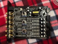
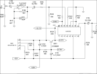
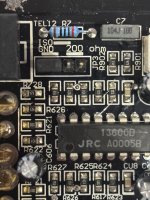
You'll have to determine the circuit components you have. The attached is a generic circuit. The output of the 13600 is determined by the current driven into pin 1 and/or 16 (only one is used for mono applications). I don't see any transistors on your board. They could be external or not used. You will need to vary the voltage feeding the base of the transistor in the diagram. When higher voltage is driving the input resistor (R124 in the diagram), the output is greater. When less voltage is driven into that resistor the output is reduced.
Attachments
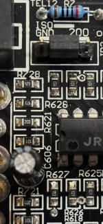
Is there a resistor between pin 1/16 and one of the terminals of the telco jack?
What value?
Are there pins that have ±15v on them?
What value?
Are there pins that have ±15v on them?
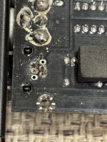
I'm not sure which is ground. What is the resistance between (no power applied, no RCAs plugged in) between:
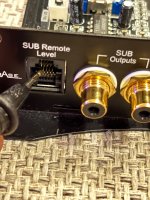
RCA shield ground and pins 4/13 of the 13600?
Primary ground and pins 4/13 of the 13600?
RCA shield ground and pins 4/13 of the 13600?
Primary ground and pins 4/13 of the 13600?

This may not provide linear control but you can try it. 10k potentiometer connected across (outer terminals) the positive and negative 14v with the center terminal feeding the two resistors that drive pins 1 and 16 of the 13600.
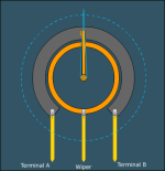
I don't know what's unclear. For the attached pot, positive 14v (connected directly [0 ohms] to pin 11 of the 13600) to terminal A on the pot.
Same for pin 6 of the 13600 to terminal B.
The wiper would go to the two resistors driving pins 1 and 16.
You want the positive terminal of the pot shorted (0 ohms) to the wiper when the pot is clockwise.
Same for pin 6 of the 13600 to terminal B.
The wiper would go to the two resistors driving pins 1 and 16.
You want the positive terminal of the pot shorted (0 ohms) to the wiper when the pot is clockwise.
Attachments
- Home
- General Interest
- Car Audio
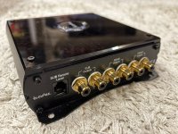
- In Phase SRC 6