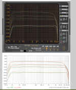
I'm calibrating a Revox B77 and these are the frequency curves. First one, slow speed, second one fast speed.
Slow speed response is pretty good.
I changed C1 on the left channel from 2.7nF to 4.7nF and the curve is now flat.
The right channel has a bump from 1 to 12k and I can't seem to flatten it out. I changed C3 to 1.5nF but that only affects the range above 10k-12k. I tried several other values (2.2nF, 3.3nF, 4.7nF) but that doesn't do the trick. The sound is not bad at all, but still one can hear the difference L/R in this sensitive area. I'm looking for ideas to improve the right channel.
Slow speed 3 3/4

Fast speed 7 1/2


Slow speed response is pretty good.
I changed C1 on the left channel from 2.7nF to 4.7nF and the curve is now flat.
The right channel has a bump from 1 to 12k and I can't seem to flatten it out. I changed C3 to 1.5nF but that only affects the range above 10k-12k. I tried several other values (2.2nF, 3.3nF, 4.7nF) but that doesn't do the trick. The sound is not bad at all, but still one can hear the difference L/R in this sensitive area. I'm looking for ideas to improve the right channel.
Slow speed 3 3/4
Fast speed 7 1/2
If the device has some decades, try refreshing it replacing the 'lytics. May happen that if they had increased its internal resistance or leackage, the device will have degraded performance. But as I can see the difference is small.
As the amplifiers are included is nfb, the individual performance depends more upon feedback components than in active components. So check resistors value too.
If the inductors has adjusting slugs, they define the high frequency characteristics. Moving slightly the slugs you can match both responses. Else (if they are fixed), you can try adding an extra small piece(s) of ferrite (from an AM IF for example) to modify their inductance.
Thanks Osvaldo.
I replaced C5 and C18 lytics. Also the input & output caps (3.3µF tantalum). I checked every resistor and they are just perfect.
Which inductor, L2, L4? They are fixed but I'll fiddle with them, however, they are behind the EQ. I'll measure the frequency response at the record level pots to see. I'm not sure what happens in the emitter circuit of Q7.
Varying L1, L3, the bias traps, does obviously nothing.

I tested with some ferrite up and around the coil and other parts of the board but that doesn't change anything.
I'm starting to think the recording or playback head is the cause.
It is strange however, that in slow speed mode the curve is flatter.
I will adjust the levels by ear as a compromise.
I'm starting to think the recording or playback head is the cause.
It is strange however, that in slow speed mode the curve is flatter.
I will adjust the levels by ear as a compromise.
Well, I wouldn't call it 'that' bad. When listening trough headphones it's good at slow speed, some 'air' is missing from the falling curve at 8-10k.
It's just that bump in fast speed that annoys.
The tape I use for testing is not new either but I get consistent results nonetheless.
It's just that bump in fast speed that annoys.
The tape I use for testing is not new either but I get consistent results nonetheless.
Last edited:
Interestingly, the user guide at http://www.anaxwaves.com/NAKT100/
shows deviations of the equipment similar to what Hugo sees ...
Jan
shows deviations of the equipment similar to what Hugo sees ...
Jan
Attachments
Yes, and these are most likely from a Nak deck. You can't hear those deviations with music.
Did you know this program, Jan?
Nifty little stuff. 🙂
Did you know this program, Jan?
Nifty little stuff. 🙂
Never had a reel-to-reel tape recorder here, but I remember that ages ago having had several cassette-deck over time and assuming that their heads were correctly aligned, sometimes cleaning and/or demagnetizing head(s) worked wonders.
Just sayin'... 🙂
Just sayin'... 🙂
Yes, the basics have to work as good as possible, thanks for the tip.
For starters I recapped the boards, mainly the Fracos who are known to be bad, no excessive overhaul.
Cleaned and demagnetized the tape path, got rid of any possible bad contacts and did some basic resolder.
Everything works as expected, it's just that bump in the frequency response that I don't like, but I'll find a compromise.
With such a machine you need to pick your favorite and intended speed for regular use.
My point is that quite often you can only properly optimize frequency response for 1 of 2 speeds.
When HF eq adjustments are used near max. to pick-up very high frequencies, you get the unwanted 'hump' you show.
A typical example is when there is different L/R head-gaps. ( usually play back heads )
It appears that @ 7.5 IPS one channel has its HF eq pot. set very 'high' to pick-up frequencies around 16K and up.
There is something known as "Peaking the Playback Head". This requires adding a small ceramic capacitor in the range of 10 to 47 pF
in PARRALEL with the playback head connections. ( one capacitor per Ch. of head connection )
If you add 10pF to your 'flat channel' and 33pF to your 'hump channel' > then re-adjust your HF eq , your frequency response problem
may be gone 🙂
PS.
As I think someone mentioned, don't play with "Bias Trap" adjustments unless you have an Oscilloscope and know the test-points.
Also, when doing any head 'connections', make sure the machine is FULLY UNPLUGED.
Hi @Netlist : you did not mention (or perhaps I overlooked it) whether the frequency response is from a calibration tape in playback mode, or from your regular tape in record/playback mode.
The usual procedure is to calibrate the playback level and EQ (IEC? NAB?) from a trusted calibration tape, and then calibrate the record level and HF boost + bias trap using your regular tape. Ideally the record frequency response is flat, but you need some HF boost due to rec head gap loss due to gap width compared to wavelength on tape.
The usual procedure is to calibrate the playback level and EQ (IEC? NAB?) from a trusted calibration tape, and then calibrate the record level and HF boost + bias trap using your regular tape. Ideally the record frequency response is flat, but you need some HF boost due to rec head gap loss due to gap width compared to wavelength on tape.
The response is from the record/playback mode, not a cal. tape, but of course I first calibrated the playback level with a 1kHz tone from a NAB 250nWb/m tape.
I carefully followed the procedure in the service manual.
The EQ settings are on page 11 section 6.4.18
More on the bias trap later. 🙂
I carefully followed the procedure in the service manual.
The EQ settings are on page 11 section 6.4.18
More on the bias trap later. 🙂
Attachments
Here are some more measurements.

Measuring point 1: Input Record amp L/R, no difference, perfectly flat.

Measuring Point 2: L/R slow speed (Pink noise, forgot to switch to sweep but you got the idea)

Measuring point 2: L/R fast speed

Measuring point 3: Bias trap slow speed

Measuring point 3: bias trap fast speed

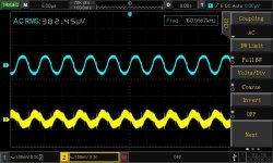
Scope picture measuring point 3: bias trap L/R slow speed

Scope picture measurement point 3: bias trap L/R fast speed

There's clearly something wrong with the bias trap although I don't think that is the cause of the bump in the frequency curve.
Bias trap voltages should be <350mV and both channels are at their lowest point, far below 350mV.
- Schematic with measurement points
- Frequency plots at these measurement points
- Scope pictures of both bias traps left & right channel
Measuring point 1: Input Record amp L/R, no difference, perfectly flat.
Measuring Point 2: L/R slow speed (Pink noise, forgot to switch to sweep but you got the idea)
Measuring point 2: L/R fast speed
Measuring point 3: Bias trap slow speed
Measuring point 3: bias trap fast speed
Scope picture measuring point 3: bias trap L/R slow speed
Scope picture measurement point 3: bias trap L/R fast speed
There's clearly something wrong with the bias trap although I don't think that is the cause of the bump in the frequency curve.
Bias trap voltages should be <350mV and both channels are at their lowest point, far below 350mV.
Attachments
The rec amplifier works as a current generator, you cannot measure the rec frequency response this way. Only make sure the bias oscillator leak level is minimum at 3.
Thanks, what do you mean with '3'?Only make sure the bias oscillator leak level is minimum at 3.
Edit: I see, measuring point 3 🙂
Last edited:
- Home
- Source & Line
- Analogue Source
- Improving on a Revox B77 frequency curve