
if you measure with a 10 dB step most things looks smooth.Incredibly even frequency (and step) response! Does this include any filter/dsp?
Very interesting, thanks for posting!
Nice magnet design, cool to use halbach on the outer sides and 2 regular ones in the middle. , it looks kind of like a rubanoide motor (with 2 gaps). you could ditch the metal in between the middle magnet, and move that magnet sideways. it might be stronger (and have 0 steel). then make it a dual coil with one reversed ? so they move in tandem.
Last edited:
Rubanoide motor 🙂 efficient , but not cool to wind indeedI have no way to measure the BL of there's magnet structures , it would be nice to know the difference between the different designs.
Around 5 years ago I tested a flat voice coil /magnet structure
View attachment 1390369
it worked well except winding a voice coil with thin magnet wires on a flat surface is past my patience level. Also keeping the flat voice coil former centered in the magnetic gap is difficult to impossible except if one uses a wide magnetic gap or a spider on top of that structure but that would likely causes issues with distortion etc. There're a piston driver with flat coil develop and one is available:https://www.parts-express.com/Dayto...ore-Neodymium-Woofer-4-Ohm-295-248?quantity=1 but these are pistons drivers not bending wave drivers
BY the way i thought a Manger was not a DML... i took 1 appart 1 year ago.. and they are indeed not a DML... the material is not like anything a DML would use... DML uses stiff material as light as possible manger. is floppy. Here a video where i still thought it might be a dml... (it aint) but they are very nice made 🙂
Last edited:
Nice thread!!
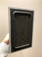
I’ve been building bending wave speakers (both flat panels and Walsh type) since a few years, using re-constituted regular drivers and exciters.
I’ve lately been learning and experimenting with my own motor design and construction.
This is one example.
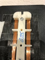
It is a flat voice coil as you can see in the pictures. It was working fine and played loud untill I got a bit excited and played to loud…smoke….
The coil is situated between two pairs of n52 10x5x100mm magnets.
I’ve built a small jigg to wind the coil and glue it to the former which is made of carbon fibre 0.15mm thick.
The whole motor structure is made in my 3D printer.
The membrane is a CF-BALSA-CF sandwich 0.15mm cf, 2 mm balsa cross grain.
I made the foam surround from EVA foam.
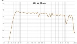
The speaker is working in both pistonic mode and bending wave.
The main purpose of the speaker was to test the motor.
The FR is after some dsp so more indicative.
Thomas
I’ve been building bending wave speakers (both flat panels and Walsh type) since a few years, using re-constituted regular drivers and exciters.
I’ve lately been learning and experimenting with my own motor design and construction.
This is one example.
It is a flat voice coil as you can see in the pictures. It was working fine and played loud untill I got a bit excited and played to loud…smoke….
The coil is situated between two pairs of n52 10x5x100mm magnets.
I’ve built a small jigg to wind the coil and glue it to the former which is made of carbon fibre 0.15mm thick.
The whole motor structure is made in my 3D printer.
The membrane is a CF-BALSA-CF sandwich 0.15mm cf, 2 mm balsa cross grain.
I made the foam surround from EVA foam.
The speaker is working in both pistonic mode and bending wave.
The main purpose of the speaker was to test the motor.
The FR is after some dsp so more indicative.
Thomas
Attachments


Uhm thats insane low 🙂 i expect it to be 1/2 ? like dynamic and dml. or BML , looks great by the way !`nice jig. I made something the same i must say it rather hard to make a perfect one 🙁 to bad the curves are to steep to use my cnc to laydown the perfect coil (or a 3d printer) on some sticky tape 🙂
I had Manger MSW years before (see first entry) and one was also broken and I disassembled it a couple of years ago too but as I thought that they are not something to repair as the magnets were heavily corroded. I was mostly interested to see the backside of the membrane and central damper before it went into the electronic waste.BY the way i thought a Manger was not a DML... i took 1 appart 1 year ago.. and they are indeed not a DML... the material is not like anything a DML would use... DML uses stiff material as light as possible manger. is floppy. Here a video where i still thought it might be a dml... (it aint) but they are very nice made 🙂
The difference between bending wave and distributed mode loudspeakers is not soft vs stiff membrane. I earliest literature I found were fairly stiff membranes (before Manger) and of course there are the bending wave loudspeakers from Göbel to mention commercially available examples.
Bending wave speakers simulate an infinite membrane as they are designed to absorb vibrational energy at the surround which means surface waves should not be reflected back. DML has a finite membrane which has no absorption at the perimeter. If one adds absorption on the perimeter of a DML it becomes a hybrid or a bending wave driver.
That is very similar to what is described in this patent review https://audioxpress.com/article/voice-coil-patent-review-two-key-resonado-patentsNice thread!!
I’ve been building bending wave speakers (both flat panels and Walsh type) since a few years, using re-constituted regular drivers and exciters.
I’ve lately been learning and experimenting with my own motor design and construction.
This is one example.
It is a flat voice coil as you can see in the pictures. It was working fine and played loud untill I got a bit excited and played to loud…smoke….
The coil is situated between two pairs of n52 10x5x100mm magnets.
I’ve built a small jigg to wind the coil and glue it to the former which is made of carbon fibre 0.15mm thick.
The whole motor structure is made in my 3D printer.
The membrane is a CF-BALSA-CF sandwich 0.15mm cf, 2 mm balsa cross grain.
I made the foam surround from EVA foam.
The speaker is working in both pistonic mode and bending wave.
The main purpose of the speaker was to test the motor.
The FR is after some dsp so more indicative.
Thomas
I can't find that company, it may be not existing anymore but https://www.parts-express.com/Dayto...ore-Neodymium-Woofer-4-Ohm-295-248?quantity=1 has it for sale and I just got one to take apart but did not find the time to play with it. Your design with 3D printed parts looks much better (especially your spider). Because it has a standard surround the membrane can move pistonic, so I think your design comes close to a BML driver. Vandersteen has pistonic midrange drivers with carbon fiber laminated end grain balsa core. Your driver has a much lower frequency response than a bending wave driver with a restrained membrane can achieve.
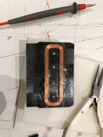
As I was curious about a flat voice coil in my design I recently built a Halbach array out of leftover magnets. I was not encouraged to pursue it further as performed less good than a rectangular voice coil (and making that voice coil was again painful).
to me dml sound .... well not so good anyway. the top end sound weird, rubanoide or BML 🙁 or any other i heard before. wont match a planar t be fair. but who knows 🙂I had Manger MSW years before (see first entry) and one was also broken and I disassembled it a couple of years ago too but as I thought that they are not something to repair as the magnets were heavily corroded. I was mostly interested to see the backside of the membrane and central damper before it went into the electronic waste.
The difference between bending wave and distributed mode loudspeakers is not soft vs stiff membrane. I earliest literature I found were fairly stiff membranes (before Manger) and of course there are the bending wave loudspeakers from Göbel to mention commercially available examples.
Bending wave speakers simulate an infinite membrane as they are designed to absorb vibrational energy at the surround which means surface waves should not be reflected back. DML has a finite membrane which has no absorption at the perimeter. If one adds absorption on the perimeter of a DML it becomes a hybrid or a bending wave driver.
A halbach might as well not deliver what you expected, i mean in same cases when using flat steel the regular rubanoide motor would be more efficientAs I was curious about a flat voice coil in my design I recently built a Halbach array out of leftover magnets. I was not encouraged to pursue it further as performed less good than a rectangular voice coil (and making that voice coil was again painful).
The Halbach arrangement is not about efficiency, but about reducing distortion. With the rubanoid, the copper sheets, 0.2mm in the air gap, are extremely important. The damping of the membrane also has to be very strong, then it can keep up with planar ones. Monteverdi, how did you operate the manger? Your own design? Greetings
This design was largely studied and developed since 1920s. Paddock and Linaeum are other ideas on the same or similar magnetic circuit. FAL (Fuyurama Audio Labs) japanese drivers are also a similar design. There are lot of these designs somewhere in DIY Audio with most of the patents. The difficulty in this designs remain the materials and the shape of the membranes... Attemps for wide range audio driver remain unsuccessful.
@ruba1 yes : unsuccessful !
Have you ever listened to one of these speakers? Have you had the opportunity to have a look to their measurements?
Personally I built several and I even currently have a project in progress with this type of engine...
Moreover, if everything had been said about these transducers, there would not be so many people who still be interested, like the DML with the exciters!
Why are you working on it if it supposedly doesn't work? It is known that there are no measurements. But there are measurements for the airfoil and the one in the photo was measured by Timmermann. Actually, this topic doesn't belong in this thread. I'm happy with my rubanoide. I rely on my ears and not on measurement diagrams.


I designed this speaker for the Manger MSW. I replaced the MSW with my design of bending wave drivers but because the cutout was for the MSW it inherited that.The Halbach arrangement is not about efficiency, but about reducing distortion. With the rubanoid, the copper sheets, 0.2mm in the air gap, are extremely important. The damping of the membrane also has to be very strong, then it can keep up with planar ones. Monteverdi, how did you operate the manger? Your own design? Greetings
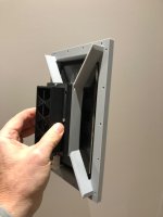
The round design has not only an aesthetic reason but also to vary edge diffraction as much as possible, therefore the decentered arrangement. These Acccuton woofers are in a vented alignment and these speakers were designed for a room were the placement was 3m from the front wall. As I moved in a different house I did not have enough space to the front (only 0.8m) wall so I decided to go the opposite direction and have a wall mounted speaker. The cross over frequency with the Mangers were around 350 Hz, I went through couple of versions including cap-less one but than I decided that such low crossover frequencies are better achieved with line level crossover, first with a simple passive RC filter. Eventually I invested in a Devialet amp which allows for digital crossover with main speaker filtered or not and pre out low pass filtered for the woofers. Presently I run my drivers full range and only filter the pre out at 200 to 250 Hz.
May I warm up the magnets discussion?
As you described in one for your first posts, this one seems to be one of your last iterations:

In order to perform some FEMM iterations, I browsed the website of supermagnete.ch to find some magnets to aproach your design. There, I found a neodyme type 45SH (rated for 150°C), 25mm x 6mm x 2mm magnet. I imagined to use a bunch of these magnets, glueing them together to an array like the one you described, thus resorting to high temperature rated epoxy. In FEMM this would look like this:

You may notice a left sided variant (original, central piece full copper) and right sided variant (with a 1mm diameter MuMetal rod inlay into the central copper core).
Indeed, running the FEMM simulation shows a disturbing > 5% |B| variance inside the gap's magnetic field for the left plain copper variant. This is not nice. Instead, a much more linear behavior is shown for the variant including the 1mm central MuMetal rod.:

The MuMetal inlay consequently then shows a beneficial effect of the field linearity along the magnet's gap height, as can be seen on the next two graphs.
Plain copper version such as left-sided variant, without MuMetal:

Right-sided version, with Central MuMetal rod inlay:

The described array needs quite a bunch of magnets, each costing about CHF 1.-. So one might be tempted to go for a more economical, "poor man's" magnet assembly, withdrawing the inner structure, thus saving the 8 inner magnets and the central copper block. Good idea? No, not really. For the next simulation the inner block's structures has been declared as material = "Air", so there is "nothing" there in the middle:

And for the gap's linearity:

As can be seen, the central part is crucial for a correct result.
Inversely, for the rich men out there requiring one full Tesla inside their's gaps ( the so called Tesla-snobs ), it may seem frustrating being faced with a gap field strength of mickey 0.9 Tesla. So go brute force, then, and double the outer magnetic structure:

Tadaa ... and there we are - one full, near-linear Tesla all along some 40mm magnet gap hight:

And for the perfecionists, and as the curve shows a max. at about 4mm, we could shift the MuMetal rod a wee bit farther away from the gap, making the whole graph look even more linear:

That's it. In real-world, one certainly would opt for the "standard" 0.9T version, and optimizing the central MuMetal inlay in order to match the precise location of the voice coil inside the gap. Most of the time the coil will not be in the mid radial center of the gap, but rather slightly lateralized.
After all these simulations, it would be interesting to real-world compare and measure the distortion figures of both a copper-only center piece vs. one with a carefully optimized MuMetal inlay version magnet assembly. A proof of concept, so to say. I guess that in case of such a 4mm-haight-linearized gap, along with a 2mm underhung coil, there might be some differences. With an overhung system along with a 10mm coil instead, rather not.
And maybe, among the magnetassemblists, introducing a piece of MuMetal may seem sexy for the linearists, but not so for the ironlessists fraction. Question then: Who might be the purists?
As you described in one for your first posts, this one seems to be one of your last iterations:
In order to perform some FEMM iterations, I browsed the website of supermagnete.ch to find some magnets to aproach your design. There, I found a neodyme type 45SH (rated for 150°C), 25mm x 6mm x 2mm magnet. I imagined to use a bunch of these magnets, glueing them together to an array like the one you described, thus resorting to high temperature rated epoxy. In FEMM this would look like this:
You may notice a left sided variant (original, central piece full copper) and right sided variant (with a 1mm diameter MuMetal rod inlay into the central copper core).
Indeed, running the FEMM simulation shows a disturbing > 5% |B| variance inside the gap's magnetic field for the left plain copper variant. This is not nice. Instead, a much more linear behavior is shown for the variant including the 1mm central MuMetal rod.:
The MuMetal inlay consequently then shows a beneficial effect of the field linearity along the magnet's gap height, as can be seen on the next two graphs.
Plain copper version such as left-sided variant, without MuMetal:
Right-sided version, with Central MuMetal rod inlay:
The described array needs quite a bunch of magnets, each costing about CHF 1.-. So one might be tempted to go for a more economical, "poor man's" magnet assembly, withdrawing the inner structure, thus saving the 8 inner magnets and the central copper block. Good idea? No, not really. For the next simulation the inner block's structures has been declared as material = "Air", so there is "nothing" there in the middle:
And for the gap's linearity:
As can be seen, the central part is crucial for a correct result.
Inversely, for the rich men out there requiring one full Tesla inside their's gaps ( the so called Tesla-snobs ), it may seem frustrating being faced with a gap field strength of mickey 0.9 Tesla. So go brute force, then, and double the outer magnetic structure:
Tadaa ... and there we are - one full, near-linear Tesla all along some 40mm magnet gap hight:
And for the perfecionists, and as the curve shows a max. at about 4mm, we could shift the MuMetal rod a wee bit farther away from the gap, making the whole graph look even more linear:
That's it. In real-world, one certainly would opt for the "standard" 0.9T version, and optimizing the central MuMetal inlay in order to match the precise location of the voice coil inside the gap. Most of the time the coil will not be in the mid radial center of the gap, but rather slightly lateralized.
After all these simulations, it would be interesting to real-world compare and measure the distortion figures of both a copper-only center piece vs. one with a carefully optimized MuMetal inlay version magnet assembly. A proof of concept, so to say. I guess that in case of such a 4mm-haight-linearized gap, along with a 2mm underhung coil, there might be some differences. With an overhung system along with a 10mm coil instead, rather not.
And maybe, among the magnetassemblists, introducing a piece of MuMetal may seem sexy for the linearists, but not so for the ironlessists fraction. Question then: Who might be the purists?
Last edited:
I was just also thinking to revisit that design as I found that shorter voice coil formers (total height from membrane to top of voice coil) have more even frequency response and less distortion. The version with the iron joke has the least distortion as it has the shorter VC but if I use a equally high VC it increases it distortion levels. So I was thinking how to make a more compact iron-less design.
Glueing magnets works quite well if one uses the right adhesive and they are in an orientation where they attract each other. The best adhesive I found is Loctite AA324 (thin coat on one side) and activator 7387 on the other side (worse are "super glues" as they are too brittle). But glueing identical poles or 90º is very challenging and screws helps a lot align these magnets. The titanium screws I used are to bulky, maybe I should try to glue the assembly and then remove the screws.
I was trying my design before adding the inner core and the results are absolutely consistent with your Femm simulation, it doesn't work!
One interesting observation is that the addition of a MU metal inlay increases the evenness but would that not cause magnetic hysteresis distortion?
The magnets I used are mostly N48H (rated 120ºC)
Last edited:
@ruba1 :
perhaps I misspoke. What I meant was that I'm still working on this type of magnetic circuit, but no longer using the method shown in this photo for example, the one that most people have been exploring for years, if not for almost a century now. Paddock, for example, was one of those who experimented extensively with this design. In fact, back in 2002, when Airfoils were first marketed, Stereophile published an interesting article: https://www.stereophile.com/floorloudspeakers/648/index.html.
If you look closely at this "driver", you can see that there are no "membranes" as such, but only surrounds...
Of course, this is just my personal view, and that's why I told you that I'm continuing to work on this geometry, but to build a "finalized" loudspeaker!
As for the method of relying solely on your ear to make a transducer, I don't think it's reliable enough. Again it's my personal point of view, but of course I completely respect your way of looking at things.
- Home
- Loudspeakers
- Planars & Exotics
- improving bending wave drivers