Im trying to understand the implications of the first cap on input to pre-amp.
Have purchased all the el-cheapo preamps being sold in my country.
Im comparing them to study differences.
Today is a bad day with brain fog. So apologies in advance if some of you consider this a stupid question.
The two caps in question are C1 and C2. If I remember right these are called input decoupling caps.
Their purpose is to remove any DC from the input signal right ?. As the input signal is off a MM turn table. I see no reason for any d/c being present on the line.
Long story short. All the other boards I have use a 1 UF cap for C1 and C2.
This particular board uses 10 Uf. In a lot of places where the other boards use 1Uf.
What are the implications of using a 10Uf cap vs a 1Uf cap on the input line ?. And can I / should I just by-pass it
Is there a s/w that can simulate the impact of changing this cap or a web page calculator where I can change this value and see the impact ?.
Attachments
The cap forms a simple 'first order' high pass filter in conjunction with the resistance the cap works into. It also serves to prevent any DC from the input entering the circuit.
http://www.learningaboutelectronics.com/Articles/High-pass-filter-calculator.php
The bigger the cap the more low bass gets through. Caps should normally be sensibly sized to give a suitable low frequency roll off point. Try the calculator in that link 🙂
They are 'coupling' caps. Decoupling normally refers to small caps placed across power supply voltage rails.
http://www.learningaboutelectronics.com/Articles/High-pass-filter-calculator.php
The bigger the cap the more low bass gets through. Caps should normally be sensibly sized to give a suitable low frequency roll off point. Try the calculator in that link 🙂
If I remember right these are called input decoupling caps.
They are 'coupling' caps. Decoupling normally refers to small caps placed across power supply voltage rails.
Last edited:

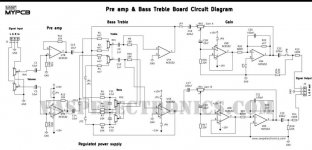
So can I assume that using 1Uf blocks everything below 7.4 Hz ?. Assuming my R value is 21.5 K.
And I can use the same formula to figure out what a 10uf would do based on my circuit ?
I am tempted to replace the 10uf cap with a 1uf cap.
It doesn't really "block everything" below 7.4Hz as such - the cutoff point is where that frequency is at half power or -3dB. Any frequencies lower than the cutoff are increasingly reduced. Have a look at this graph:

1uF with 100k in your original schematic gives a cutoff of around 1.60Hz, which is absolutely fine.
1uF with 100k in your original schematic gives a cutoff of around 1.60Hz, which is absolutely fine.
So what I use here hardly matters. Is my conclusion right ?.
Yep, it is 🙂. There will be a small bit of phase shift at the very lowest frequencies, but that's honestly not worth worrying about.
Your posts hurt technical eyes with such writing errors. Please: it is µF, kW, V, A, kOhm, DC, AC etc. It costs nothing to write stuff correctly.
Correct formula is:So its basically working as a high pass filter ?. To the opamp.
My options 10Uf / 100k = 0.1592356688 Hz
Or
1uf / 100k = 1.5923566879
So what I use here hardly matters. Is my conclusion right ?.
f = 1 / (2 * pi * R * C)
However, result values in the post are correct
View attachment 1104865
So can I assume that using 1Uf blocks everything below 7.4 Hz ?. Assuming my R value is 21.5 K.
And I can use the same formula to figure out what a 10uf would do based on my circuit ?
I am tempted to replace the 10uf cap with a 1uf cap.
I think the others have pretty much covered it 🙂
Provided you know 'R' the formula will work correctly. It is very instructive when you are learning to try different values and see at what point you start to notice things change. For example, you could try a 0.1uF and even a 0.01uF and get a feel for what happens.
So my new project is to build a class A pre-amp. To compare to all my opamp based pre-amp projects.
I was looking at this circuit.
https://www.videorockola.com/proyec...reamplificador-discreto-con-control-de-tonos/
I am confused how to apply the formula to this circuit. He says.
So Im thinking in the earlier case I was setting a limit on how low a freq can get thru. And in this case we are looking at how high a freq can get thru.
But Im not able to enter this up in something like X-Sim. Or any of the online calculators or even do the math. Because the circuit looks diffirent.
Can you help ?. Break it down.
If its that the first post was fixing the lowest Hz allowed and this is the highest. Why not just have two caps ?. One that cuts the low end and one that cuts the top. Would it be as simple as just using 2 caps ?.
The range of values he is talking about from 33pf to 470nf is huge.
I was looking at this circuit.
https://www.videorockola.com/proyec...reamplificador-discreto-con-control-de-tonos/
I am confused how to apply the formula to this circuit. He says.
So if my understanding is right in the first post I was deciding if I should use 1 Uf or 10 Uf. Now same story but the values Im looking at are much smaller.One point to consider is the input decoupling capacitor. If we observe, in the photo it can be seen that it is 0.033 uF (333), but in the diagram and in the component mask it is 0.47 (473). If a higher low pass is desired, its value can be raised up to 0.47 uF (474). But if you want a finer sound, you can set it to 0.033 uF (333).
So Im thinking in the earlier case I was setting a limit on how low a freq can get thru. And in this case we are looking at how high a freq can get thru.
But Im not able to enter this up in something like X-Sim. Or any of the online calculators or even do the math. Because the circuit looks diffirent.
Can you help ?. Break it down.
If its that the first post was fixing the lowest Hz allowed and this is the highest. Why not just have two caps ?. One that cuts the low end and one that cuts the top. Would it be as simple as just using 2 caps ?.
The range of values he is talking about from 33pf to 470nf is huge.
Attachments
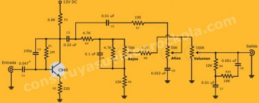
You need to know the input impedance in order to choose a suitable cap.
The input impedance is very approx the emitter resistance (220 ohm) multiplied by the gain of the transistor (lets say 100) which gives 22000 (ohms). There is a bit more to calculating it than that but that gets you 95% of the way there for your circuit.
So a 0.047uF cap would give a -3db point of approx 150 Hz for that first stage. I suspect C3 will need to be larger as well if you want to extend the LF range.
It is usually undesired to keep the frequency response high at very low frequencies, because the circuit will take too long time to stabilize itself at the operating point(s) and low frequency variations in the power supply amplified will make the cone of the woofers (or the lower frequency speakers in your set up) to move slowly without emitting sounds, with a consequence of overheating both voice coil and output stage, and increasing distortion because of the voice coil goes out of the center where the magnetic field is linear, and intermodulating thanks to Doppler effect in the transducers.
Unless it's a phono preamp where -10db at 10hz works better.I always preffered to build the rumble filter right into the first amplification stage or into the input capacitor .It helps a lot with the thermal regime too.Less subbase, less thermal dissipation, lower noise...
PLEASE, it is uF, NOT UfI should use 1 Uf or 10 Uf.
You don´t notice it but to us it´s like nails screeching on a blackboard.
But Im not able to enter this up in something like X-Sim.
did you try LTspice ?
https://www.diyaudio.com/community/...ding-ltxvii-from-beginner-to-advanced.260627/
- Home
- Source & Line
- Analogue Source
- Implications of cap value on input.