These are my conclusions for the dilemmas involved in implementing current limiting in self-oscillating post-filter class D amplifiers:
- The most natural implementation of current limiting for self-oscillating post-filter class D amplifiers are 2 additional phase-shift self-oscillating loops, one for positive current and another for negative. This technique does not disturb the recovery of the main phase-shift oscillator, which can start oscillating at wrong frequency if high gain and some conditions not met.
- There is one special case where this is the simplest solution to implement, this case is when the amplifier is full bridge in nature and modulator is grounded to one output lead of the amplifier.
- For rest of cases phase-shift oscillating current limiting is the most complex solution to implement.
- Looking for a simple solution for rest of cases, the idea of current limiting based in Vds sensing of output FETs rises.
- This solution is the one implemented in well known International Rectifier gate driver ICs.
- The current limiting in IR gate drivers can be wired for self-oscillation at a frequency similar (not much lower) to that of a self-oscillating modulator, rather than just timed shutdown.
- But this is peak-current self oscillation, without slope compensation, so it has no ability to damp any resonant circuit it is driving, like a class D output filter. What these ICs are lacking is some built-in slope compensation, at a fixed value suitable for most cases, considering 150~200V FETs available, providing some damping so that less "hash" is generated at output.
- During current limiting this results in dirty waveform with high ripple. The advantage factor of Rds-on sensing is that about 2x the current is available at 25C w.r.t. 125C. This in most cases keeps current limiting far from operating region in normal conditions.
- To implement short-circuit detection in this case (as the IR gate driver would never shut down otherwise) a CSD pulse proximity detector can be used, that only shuts down the gate driver if two CSD pulses come in too short a time interval. This happens as output approaches 0V and self oscillating frequency of current limit mode increases. This also covers the case of a shorted FET.
- The current limiting in IR gate drivers can make post-filter self-oscillating modulators start oscillating at the wrong frequency, as phase and gain clamp tricks are what make these modulators safe with high gain, which introduces 2 possible oscillation modes. The tricks must be right.
- Protection against sustained oscillation at too low Fsw is recommended with high gain modulators. This prevents amplifier destruction in case of cold solder joints or single part failures. As oscillation pattern can be complex during current limiting (depends on phase of main loop when current limiting interrupted), the limit has to be set high, like Fsw/3, and the time long enough to discard normal clipping events where Fsw also goes below idle Fsw/3.
- For BTL-loaded single-ended modulators there is always one gate driver IC that will start limiting current before the other, and this will cause it to
fold back and fall into short-circuit detection at high overdrive ratio, as output voltage gets closer to middle, but this overload ratio is about 5dB,
enough for covering the case where cold voice coil resistance results in some current limiting, in tight applications.
- For BTL-loaded single-ended post-filter feedback modulators, the current limiting in IR gate drivers imposes that each modulator must have its own current limiting, joining current limitings of different modulators (to prevent foldback) disturbs both, it makes one to work against the other when coming out of current limiting, so both modulators enter the wrong lower-Fsw oscillating mode. There is no way to improve over those ~5dB.
- For full bridge BTL post-filter feedback modulators the current limiting in IR gate drivers imposes that CSD (over-current shutdown) pulse pins have to be joined.
- Separate current limiting in this case causes one IC to keep one side ON permanently while the other IC is the one that does the current limiting. This momentarily introduces high CM component in output.
- In this case, when recovering from limiting the self oscillating loop becomes highly disturbed by the common-mode offset, resulting in clipped comparator input bouncing for some time between extremes, as the modulator has trouble damping CM energy stored in output filter. No matter if 2 or 3 caps output filter approach.
- But, when there is some distance between the IR chips (hardwired into BTL), extra parts are required for boosting CSD pin current, to keep the disable pulse short (2us), as timing in IR chips is governed by internal 100uA current source and circuit parasitic capacitances!! This is other field where these chips can benefit from improvement: at least 250uA CSD current (or 500uA for driving external circuits and intenrally limiting minimum shutdown time to 1~1.5us which is optimum for most class D purposes) instead of 100uA, and tighter tolerance than just +/-30%. For simplest designs that just shut down it would be a matter of using a bigger CSD capacitor.
- Full bridge BTL with joined current limiting pulses does not have the 5dB overdrive limit and result in minimal disturbance of self-oscillating loop, minor bounce when recovering.
For post-filter feedback self-oscillating class D my recommended method for testing current limiting and modulator recovery stability is playing "sparky" with load and scrap or cheap output terminals, setting up for 30A or more peak limit, applying 1:10 burst sine input signal with some overdrive so that clipping results without load, and moving loose output wires around binding post holes to make them spark badly, 1~3r load (or whatever low impedance to obtain current overload) in series with >10uH (or whatever inductance so that there is not much resistive loading at >20khz, which helps hiding problems).
Last edited:
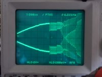
The beauty of wrong: This picture shows what happens when two high gain self-oscillating post-filter feedback modulators are loaded BTL and the CSD pins of the IR gate drivers are joined in attempt to avoid short circuit detection at >5dB overload.
Attachments
...you forgot to publish your solution. 😛
From my perspective the concerned chips look like IR would neither have intended to implement a cycle by cycle current limit nor a fixed 1-2us blanking with the CSD input.
So I would not complain if this needs extra efforts. I am already glad that there is a pin which indicates that the Vds detection got triggered and at the same time allows to control shut down duration. Even better - it allows fast control while it never was intended for this.
If you do not want to settle your custom solution at the CSD pin on your own, then contact IR/Infineon. Put reference to products with IR chips designed by you and which where build in sufficient volumes to let the marketing guy trust that you are not just a DIYer. With some good luck they will understand that your proposals for improvement make sense. In second step their R&D guys will see that the upgrade won't need rocket science inside the chip. Then IR/Infineon will ask their lead customers if they would appreciate such improvements and if these customers also understand the topic and agree - then in a few years you might see this feature in real parts.
They won't send you a medaille or anything, but with some good luck you might find future chips more according to your taste. ...which will then enable the copy cats to build better amps....
Remember one human can love another for many reasons, even for no reason (that paying the learning can become some reason), but only an inventor can love another inventor for being an inventor.
Hi there 😉
Been idle for a while (don't ask).
How about a good old output series sense resistor (series with L, before C) with a LTP sense amp modulating the input signal above two set thresholds?
Regards,
Adam
Been idle for a while (don't ask).
How about a good old output series sense resistor (series with L, before C) with a LTP sense amp modulating the input signal above two set thresholds?
Regards,
Adam
if it cannot be avoided then you need an oscillation detector connected to any circuitry that automatically shut it up.
I'm in love. 😀...but only an inventor can love another inventor for being an inventor.
I agree on modulating the amp input with a fast limiter above a first threshold. If this is implemented well, then a second threshold (which usually will never be touched) can be used for emergency shut down. The charming thing with this method is that the switching frequency of the self oscilating amp remains low when the limiter is working.Hi there 😉
How about a good old output series sense resistor (series with L, before C) with a LTP sense amp modulating the input signal above two set thresholds?
But regarding current sensing I clearly prefer to sense the drain source voltage drop, because this drop tells you when the chip inside reaches its limit. Pafi has published a simple discrete method somewhere here in the forum.
- Status
- Not open for further replies.
- Home
- Amplifiers
- Class D
- Implementing current limiting in self-oscillating post-filter feedback class D