Because they aint really CCS's, they are gyrators in fact, and they will work as intendedDear Sajti,
thanks a lot I didn't get the point then...sorry!
I'm now therefore just wondering - because I am really trying to understand - why Elvee proposed that circuit with the 2 ccs than, if it doesn't work...
Thanks again,
GM
I'm now therefore just wondering - because I am really trying to understand - why Elvee proposed that circuit with the 2 ccs than, if it doesn't work...
Elvee's circuit works. This is very special ccs, which is ccs for AC signals, but kind of servo circuit for the DC signals. THis is why it keeps the output DC balance, and gives nice high input impedance. I will give it a chance to try in my hibrid amplifier.
Regards:Sajti
Hello!
Did you try Elvee's circuit in your gear? Does it work?
I'm still studying but I will try for sure asap.
Thanks a lot!
GM
Did you try Elvee's circuit in your gear? Does it work?
I'm still studying but I will try for sure asap.
Thanks a lot!
GM
I'm trying the schematic of the post before, but it is not working, the bias is increasing a lot and blow the fuse.
I've checked many times: with the resistors works with the circuits no.
Is it possible a auto oscillating?
By the way is anybody so kind to have a look to the schematic and say if everything seem all right?
Thanks a lot!!
GM
I've checked many times: with the resistors works with the circuits no.
Is it possible a auto oscillating?
By the way is anybody so kind to have a look to the schematic and say if everything seem all right?
Thanks a lot!!
GM
1) Check without load: is the fuse blowing, what is the DC voltage at the output?
2) In case the fuse is still blowing, short the bases of BD139/40.
Everything should be quiet. Report.
2) In case the fuse is still blowing, short the bases of BD139/40.
Everything should be quiet. Report.
turn the 1k VR bias adjuster to zero ohms.
power up the amplifier through a bulb tester.
measure the voltage between D1 and D.
report back.
If that voltage is too high then you will need to short out one or more of the bias voltage setting diodes. Then power up and re-measure the bias voltage D1 to D.
The bias voltage should increase as the 1k VR is turned to higher resistance.
Hello,
thank you for your advices!
The PS fuse blow because two final BJTs (I mounted 4x2sc3281 and 4x2sa1302) one PNP and one NPN were shorted probably due to an auto oscillation (or solder wire or similar or...I don't know) when I powered on again after installing the two Gyrators.
Changed them, now things seem to work. The DC offset at outputs is approx 230mV.
I installed a trimmer of 1K on one Gyrator (instead of the 1K 1% fixed resistor) I can now reduce the offset down to 20mV and it is quite stable.
I have to experiment ( and listen 🙂 ) a little bit more and I will report measurement too.
GM
Last edited:
Dear Elvee,
everything is working fine now, but one problem occured: even if the diodes are on the heatskin the bias voltage is not stable as in the past with no Gyrators (with the 2 resistors).
The offset raised up fast at the beginnig (first 30min) and slow after 2-3 hours. This is normal, the problem is that it never goes down (except if I trim it, of course). After 6 hours still very slowly but still rising up.
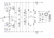
The pre-drivers and drivers supply is stabilized (not as you see in the schematic), so it cannot the cause.
I think the bjts of the girators have they influence in this, they are not on the heatskin also because far away from it.
I repeat that when I had the resistors instead of gyrators, everything worked fine: at a certain point the bias was stable around a certain value...
Everywhere I used 1% 50ppm resistors.
Any suggestion? THANK YOU!
GM
everything is working fine now, but one problem occured: even if the diodes are on the heatskin the bias voltage is not stable as in the past with no Gyrators (with the 2 resistors).
The offset raised up fast at the beginnig (first 30min) and slow after 2-3 hours. This is normal, the problem is that it never goes down (except if I trim it, of course). After 6 hours still very slowly but still rising up.
The pre-drivers and drivers supply is stabilized (not as you see in the schematic), so it cannot the cause.
I think the bjts of the girators have they influence in this, they are not on the heatskin also because far away from it.
I repeat that when I had the resistors instead of gyrators, everything worked fine: at a certain point the bias was stable around a certain value...
Everywhere I used 1% 50ppm resistors.
Any suggestion? THANK YOU!
GM
Last edited:
tells me that you powered up a part completed mains powered project direct off the mains without a bulb tester wired into the primary feed to the mains transformer.The PS fuse blow because two final BJTs............... one PNP and one NPN were shorted
The bulb tester even prevents blowing a fuse.
Dear Elvee,
everything is working fine now, but one problem occured: even if the diodes are on the heatskin the bias voltage is not stable as in the past with no Gyrators (with the 2 resistors).
The offset raised up fast at the beginnig (first 30min) and slow after 2-3 hours. This is normal, the problem is that it never goes down (except if I trim it, of course). After 6 hours still very slowly but still rising up.
The pre-drivers and drivers supply is stabilized (not as you see in the schematic), so it cannot the cause.
I think the bjts of the girators have they influence in this, they are not on the heatskin also because far away from it.
I repeat that when I had the resistors instead of gyrators, everything worked fine: at a certain point the bias was stable around a certain value...
Everywhere I used 1% 50ppm resistors.
Any suggestion? THANK YOU!
GM
It is normal that the circuit is less stable with the gyrators than without: many more components come into play, and each of them will tend to increase the dispersion if there is no global DC servo.
It is important to distinguish two types of drift:
The quiescent current is linked to mismatches inside the Vbe/Bias/emitter resistors loop. Putting the diodes and the transistors on a common heatsink will help in this instance, but will have no effect on the offset.
The offset will be governed by the symmetry: supplies, resistors, transistor's Hfe.
If a drift occurs in this department, you should keep each pair of transistors at the same temperature: Q1 coupled with Q2, BD139 with BD140, etc.
You should certainly keep the gyrator's transistors well away from any heat source, including the OP transistors.
The leakage of C1 and C2 is very important too: are they correctly installed?
Dear Elvee,
thank you for your answer!
I can tell you:
- C1 and C2 are correctly installed and are SANYO OS-CON capacitors
- when I say "BIAS" I intend "quiescent current", NOT offset. The offset infact is quite stable (I put a 200 Ohm Bourns 20-turns trimmer in series with a 900 Ohm resistor on one gyrator, instead of the 1K resistor, so I can finely trim the offset down to around +-20mV)
- the driver and final bjts + all diodes are on the same heatskin. The pre-drivers not.
- The two gyrators are far from the heatskin but still inside the case, therefore they are influenced by the internal temperature that rise also up.
I understand...with the gyrators everything is less "fixed" than with the resistors, as it was in the past.
I can tell that if I trim the quiescent current too low, then the amplifier takes too long to get to the right value... If I trim the quiescent current to be at the right value within for example 30 minutes, then it will continue to rise up too fast, and after 3-6 hours is too high...
However if I can do nothing I will survive with this issue (not a really bad one); in the actual use I don't listen to music more than 3 hours at time...or...I have to come back to the 2 x 47K resistors: thing that I probably would do for "heavy" use of the amplifier (example parties or 80db 4 ohm effincency loudspeaker or similar...)
Would be interesting to compare measurement and sound with the two configurations but at the moment I do not remember well the previous one...
Thank you then,
if you have other suggestion will be very welcome!
GM
Last edited:
Offset and quiescent current are quite different.
It is indeed likely the drift of Iq is higher with the gyrators: the DC resistance they synthetize is ~=R1(R3/R2), which is smaller than the original 56K, and they are not thermally compensated
Additionally, the increase in current density in the compensating diodes also marginally decreases their compensating ability.
You could compensate the gyrators and slightly increase their apparent resistance by adding a diode in series with R2, and increasing R1 to 2.2K.
You could also increase the compensating effect of the diode string by choosing larger types (1A or 3A) and adding one more in the string.
If you combine all those modifications, you'll probably end up with an over-compensation, with Iq decreasing when the amp heats up.
Dear Elvee,
I tried your mods but they only slightly attenuated the speed of rising up...
We are talking about after 30minutes the total quiescent current is 300mA, I very accurately trim it but slowly but continuosly, after 8 hours is 1A!
The problem (I think) is that the gyrators bjts yes are on the PCB but they are however influenced from the internal temperature of the amplifier case, that is not cold at all.
Is there a possibility to thermally compensate the gyrators? (My knowledge is very basic, I don't know, maybe is possible to use NTC instead of the normal 1% 50ppm resistors? or other ways...).
If it can help you, as I repeat, when I had the two 47.5K resistors (also on the PCB, same position where the gyrators are vertically mounted now) instead of the gyrators, after 30 minutes I could fix the quiescent to total 500mA and after 8 hours was still stable around 530 to 550 mA...
Thanks!
Last edited:
If you have 7 diodes in the string, plus the gyrators thermally compensated, I don't see what more could be done.
Except perhaps also put the gyrators diodes on the main heatsink.
Except perhaps also put the gyrators diodes on the main heatsink.
Thanks Elvee, I will carefully check again everything and report results to you hopefully they will be useful also for you!
I've used in series with R2 56K (and to the opposite one) diodes 1N4148 (is that ok?). I will put also these on the heatsink.
I've used as a 7th diode of the string a 3A Shottky one (0,2v gap), with a silicium one the 0,7 volt gap was too high the quiescent current started too high also with trim at zero resistence.
Thanks!
That's OKI've used in series with R2 56K (and to the opposite one) diodes 1N4148 (is that ok?). I will put also these on the heatsink.
You have to use 7 identical diodes, all 1A or 3A (standard, like BY254) as I said, the voltage should be OK.I've used as a 7th diode of the string a 3A Shottky one (0,2v gap), with a silicium one the 0,7 volt gap was too high the quiescent current started too high also with trim at zero resistence.
- Status
- Not open for further replies.
- Home
- Amplifiers
- Solid State
- implement CCS on a BJT darlington buffer