Hi there,
I’ve done a fair amount of searching and watching YouTube tutorials etc and although I think understand what impedance basically is from the standpoint of a dynamic loudspeaker (driver) and acoustic impedance (air), I’ve found nothing really explaining how they interact. Though I understand it is complicated.
Most information simply tells you how to read the impedance plots/simulations, with very little on the practical uses/implications of it.
I’m interested in bass horns and quarterwave resonators particularly. I’ve heard Tom Danley talking about ‘impedance transformation’ and I think this is what I’m interested in specifically.
Thanks
Understanding speakers requires a lot of math. While mostly directed to ported boxes, the Thiele/Small parameters are a good foundation.
https://en.wikipedia.org/wiki/Thiele/Small_parameters
Perhaps Tom Danley is talking about compression horns, where the horn attempts to improve the acoustic loading on the driver for better efficiency? This comes with a compromise in frequency response and distortion. For bass, the best acoustic coupling and cleanest response comes from a large diaphragm.
Ok, I’ll have a read through the whole article.
I know what all of the T/S parameters that are mentioned by manufacturer specifications refer to, but not much more than that.
I also understand basic horn theory in terms of directivity and impedance matching, but it’s more the details of impedance response that I’m wondering about. It’s extremely complicated, I know, but I was interested to see if there is a layer of said complexity with a few rules of thumb that I could grapple with.
I mean, I’m probably imagining things wrongly, but hypothetically, even with the impedance of the driver matched to the air perfectly, the movement of a piston is not the same as the natural movement of air in response to natural sound sources.
This is the kind of thing I’m interested in, though again I realise it’s massively complicated.

I’m interested in bass horns ... I’ve heard Tom Danley talking about ‘impedance transformation’ and I think this is what I’m interested in specifically.
A horn acts as an acoustic transformer, changing high pressure, small amplitude (high impedance) vibrations of the diaphragm in its throat into low pressure large amplitude (low impedance) vibrations of the air at its mouth.
(To put it in very simple terms, the vibrating diaphragm of a loudspeaker driver is very stiff whereas the air is very floppy. The exponential shape of a horn is instrumental in improving the transfer of energy from the stiff diaphragm to the floppy air.)
An electrical analogy is a valve amplifier output transformer that changes high voltage, low current (high impedance) electrical signals within the amp to low voltage, high current (low impedance) electrical signals at the loudspeaker.
That's the simple stuff, where do you want to go from here?
Last edited:
To add a little bit more to Galu's succinct summary of the basics, when a horn acts as an acoustic transformer, it effectively gives the driver something stiffer to push against.
That typically results in the Electrical Impedance of the system increasing as well.
One example I like to illustrate this is EAW's SB1000 series of subwoofers. They are technically Bass Reflex but have the drivers mounted on angled baffles, which creates a flared cavity at the front of the box.

Helpfully, EAW also publish unprocessed frequency response graphs and impedance curves for these.

We can see that at a narrow range of frequencies, corresponding to where the depth of the cavity is about 1/4 of a wavelength, the cavity is providing acoustic gain (the hump in the frequency response) and a matching increase in the electrical impedance.
Hope having a real world example helps a bit.
Cheers,
David.
That typically results in the Electrical Impedance of the system increasing as well.
One example I like to illustrate this is EAW's SB1000 series of subwoofers. They are technically Bass Reflex but have the drivers mounted on angled baffles, which creates a flared cavity at the front of the box.
Helpfully, EAW also publish unprocessed frequency response graphs and impedance curves for these.
We can see that at a narrow range of frequencies, corresponding to where the depth of the cavity is about 1/4 of a wavelength, the cavity is providing acoustic gain (the hump in the frequency response) and a matching increase in the electrical impedance.
Hope having a real world example helps a bit.
Cheers,
David.
That's interesting, David.
Your graphs would appear to indicate that the electrical impedance of the loudspeaker is not only dependent on mechanical and electrical factors, but also on the acoustic impedance seen by the speaker diaphragm.
From a different perspective, this paper talks about determining the acoustic impedance seen by the speaker diaphragm by measuring the electric impedance of the device.
https://www.sciencedirect.com/science/article/abs/pii/S0003682X1730227X
I built some boxes where a 12" fired backwards through a narrow slot so that the box resonance was lower than normal, but the compression chamber creates a resonance, which I filled as much as possible with Styrofoam. I'm not sure it was worth the extended bottom end. Pretty much any acoustic device has resonances that can be a real headache, so for most personal use, a simple box is best.
Your graphs would appear to indicate that the electrical impedance of the loudspeaker is not only dependent on mechanical and electrical factors, but also on the acoustic impedance seen by the speaker diaphragm.
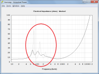
The attached chart compares the magnitude of the electrical input impedance of an exponential horn loudspeaker radiating into free space (grey trace) to that of the same loudspeaker radiating into eighth space (black trace). The only input condition that has changed is the acoustical impedance loading the front side of the driver diaphragm.
The chart results show that the electrical input impedance is reduced when the acoustical impedance is increased by switching from free space to eighth space.
This is because:
Zem = Bl ^ 2 / Zm
Where:
Zem = Motional electrical impedance
Bl = Driver magnetic flux density x voice coil conductor length
Zm = Total mechanical impedance
It can be seen from the above formula that for a constant Bl, increasing Zm, which includes the total acoustical impedance Za (Ra + j * Xa) converted to mechanical impedance, will reduce Zem (Rem + j * Xem), which forms part of the electrical input impedance Ze.
Zm = Rms + Sd ^ 2 * Ra + j * (w * Mmd - 1 / (w * Cms) + Sd ^ 2 * Xa)
Ze = Re + Rem + j * (w * Le + Xem)
Attachments
- Home
- Loudspeakers
- Subwoofers
- Impedance response