Impdeance of ESL varying with freq?
Hi
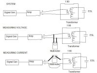
I have been trying to measure the input impdeance of my transformer's primary with my DIY ESL connected at the secondary. I am using a signal generator and a digital true RMS multimeter to measure the input voltage(Vrms) and then the input current(Irms). I then calculate Zin=Vrms/Irms. As expected the impedance has fluctuated wildy with frequency from 120 down to 0.3ohms.
What wasn't expected is the variation of the input impedance with the input voltage and power level. At low frequencies the input impedance appears to decrease quadratically with increasing input voltage. I have gotten similar results at several low frequencies. At high frequencies the input voltage and power doesn't seem to have an effect on the input impedance.
Anyone have any explanations on this behaviour?
Thanks
Pete
Hi
I have been trying to measure the input impdeance of my transformer's primary with my DIY ESL connected at the secondary. I am using a signal generator and a digital true RMS multimeter to measure the input voltage(Vrms) and then the input current(Irms). I then calculate Zin=Vrms/Irms. As expected the impedance has fluctuated wildy with frequency from 120 down to 0.3ohms.
What wasn't expected is the variation of the input impedance with the input voltage and power level. At low frequencies the input impedance appears to decrease quadratically with increasing input voltage. I have gotten similar results at several low frequencies. At high frequencies the input voltage and power doesn't seem to have an effect on the input impedance.
Anyone have any explanations on this behaviour?
Thanks
Pete
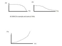
Here is another sketch showing the trend in impedance as a function of input voltage and as a function of input power. I also included a sketch of input power as a function of Vin since it wasn't immediately obvious to me that the two graphs agreed.
Attachments
OK, what you want to do is to use a series precision resistor between the amp and the speaker. Derive the current from the voltage drop across the resistor.
I know of this method but what was wrong witht he one I was using? How are these results explained?
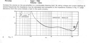
As you have discovered the impedance at any given frequency is a function of many factors. I THINK the variation with power that occurs at low frequencies is because the amount of power coupled to the air is a larger (smaller?) fraction of the total power dissipated. You are not the first person to have seen this behavior. The attached image is from the Quad ESL-63 service manual.
Are you doing these measurements with DC bias applied to the diaphragms? I think you will find the impedance changes if you turn the bias on and off.
The meter has a precision resistor inside it (called a shunt, used when measuring current), so the only reason to use an external resistor is if your meter is more accurate at reading voltage than current. I would not expect the resistance of the shunt to change during your tests.
I_F
Attachments
I have been testing with the bias supply on so the ESL makes noise. I will test with it off and after long enough for most of the charge to leak away. I will also compare the two testing methods.
I was not confident with my results because the amp I use has two 32Vrms secondary windings giving rails of about +/- 45VDC which should mean the maximum Vrms measured at its output was 45/sqrt(2)=32Vrms(unsurprisingly!) but I got a reading of 44Vrms??? Any ideas?
This variation with power level makes it very difficult to design an amplifier for low frequencies since I don't know the impedance it will drive. If the impedance trend continues as voltage increases the impedance will be very very low with the voltages I am planning to apply.
Pwoida said:I know of this method but what was wrong witht he one I was using? How are these results explained?
Much of this difference may be something simple like your meter changing ranges- that causes the internal resistance of the meter to change. The quasi constant current method (using a constant series resistor) avoids those errors and is much more accurate.
Post #8
I have been testing with the bias supply on so the ESL makes noise. I will test with it off and after long enough for most of the charge to leak away.
Hi,
Measuring with bias off will change the impedance because of the negative capacitance that comes from the membrane being charged.
örjan
Pwoida: Which multimeter are you using?
Can the multimeter handle frequencies up to 20 kHz in both voltage and current? Not all multimeters can do that!
Can the multimeter handle frequencies up to 20 kHz in both voltage and current? Not all multimeters can do that!
It's the low frequencies that I am having trouble with. I have measured only a slight difference with the bias on compared with the bias off.
I HAVE A THEORY!
As I mentioned in a previous post I was getting more RMS voltage than I should be able to obtain with the voltage rails and a sine wave. This must mean the amplifier is clipping and producing something closer to a square wave. This would create high frequencies and hence these would see a low impedance and draw larger currents. The more I increased the voltage the more clipping and the more current. Hence I detect a falling impdeance as voltage is increased!
However I have detected similar(but slightly more moderate) behaviour with an amplifier with high enough voltage rails.
I will keep testing and post any findings.
A valid question.
I have always been curious, and ever so slightly uneasy, about the label applied below 200Hz on the impedance curve of the Quad 63 that reads “level dependent”. I have not satisfied myself as to why this non-linearity exists to a significant enough degree that Walker felt it necessary to call it out. Here are some possibilities, thrown out without a lot of analysis or research on my part:
1.) Mark, with your “turn off the bias” comment, you seem to be implying that constant charge assumption may no longer be applicable, and that diaphragm charge is varying with signal. Maybe I’m reading too much into what you said. But perhaps the 10M series HT resistor and neon bulb plus the diaphragm resistance is not enough resistance to meet the 2fRC>1 criterion at these bass frequencies. This seems plausible. Still the Quad’s bass seems very clean to me (at least up to a limit), compared to the many significant non-linearities of moving coil bass cones.
2.) The input impedance due to primary inductance of the step-up transformers drops gradually below 200Hz. The secondary is lightly loaded and the input current is a non-linear function of voltage due to B-H non-linearities. Perhaps if driven by a true voltage source amp, much of this factor of impedance non-linearity is not transferred to the air.
3.) The intended operating range of ESLs is where the radiation resistance exceeds diaphragm stiffness reactance (due to stretch or springiness). Think of a series RL circuit. As frequency decreases, stiffness reactance starts to become comparable to and then exceeds the radiation resistance. The stiffness reactance of a stretched plastic film is bound to be non-linear, and the linear radiation resistance gives way to this non-linearity at low frequencies. The effect would show up in the impedance curves, as well as in the airborne response.
4.) Mark, you said “I THINK the variation with power that occurs at low frequencies is because the amount of power coupled to the air is a larger (smaller?) fraction of the total power dissipated.” I don’t see how radiation loading by itself is a non-linear function, but perhaps you were thinking of these other factors.
So, I don’t know which of these is at “fault”. It could be that more than one of these factors is at play at once.
Any further insights from anyone?
I've been thinking about this too. I can't remeber ever seen a review where the impedeance varies with signal ampitude, except for the esl63.
One other datapoint though. Baxendall writes in "Loadspeaker and Headphone Handbook" describing the esl57s sound stepup transformer:
"The loading choke...will also be ignored. It consists merly of of a few shorted turns round the transformer core and its pupose is to reduce the magnitude of the input impedeance peak that occurs somewhere in the 100 Hz region - thr actual frequency is very dependent on the signal amplitude"
What would be intresting is if there is other esls known that does not have these impedeance variations.
örjan
Interesting. To my knowledge the ESL-63 has shorted turns only in the delay line inductors, which I believe to be air core, but not in the step-ups. I would be surprised if other ESLs do not exhibit this impedance non-linearity. Walker was just more honest. And ingenious.
Re: A valid question.
The bias creates a negative compliance which changes the resonant frequency of the diaphragm, among other effects. That change is reflected in the impedance value, so the impedance will differ depending upon whether the bias is applied or not (and the bias voltage). The correct way to perform the measurement is with the bias on, of course, because that's how the speaker will be used.
I think you have that upside down- as the frequency decreases, the reactance of an inductor decreases. But, how do you decide if the reactance is capacitive or inductive, and over what range of frequencies...?
Probably! Things are often more complicated than they look.
I_F
Brian Beck said:I have always been curious, and ever so slightly uneasy, about the label applied below 200Hz on the impedance curve of the Quad 63 that reads “level dependent”. I have not satisfied myself as to why this non-linearity exists to a significant enough degree that Walker felt it necessary to call it out. Here are some possibilities, thrown out without a lot of analysis or research on my part:
1.) Mark, with your “turn off the bias” comment, you seem to be implying that constant charge assumption may no longer be applicable, and that diaphragm charge is varying with signal. Maybe I’m reading too much into what you said. But perhaps the 10M series HT resistor and neon bulb plus the diaphragm resistance is not enough resistance to meet the 2fRC>1 criterion at these bass frequencies. This seems plausible. Still the Quad’s bass seems very clean to me (at least up to a limit), compared to the many significant non-linearities of moving coil bass cones.
The bias creates a negative compliance which changes the resonant frequency of the diaphragm, among other effects. That change is reflected in the impedance value, so the impedance will differ depending upon whether the bias is applied or not (and the bias voltage). The correct way to perform the measurement is with the bias on, of course, because that's how the speaker will be used.
3.) The intended operating range of ESLs is where the radiation resistance exceeds diaphragm stiffness reactance (due to stretch or springiness). Think of a series RL circuit. As frequency decreases, stiffness reactance starts to become comparable to and then exceeds the radiation resistance. The stiffness reactance of a stretched plastic film is bound to be non-linear, and the linear radiation resistance gives way to this non-linearity at low frequencies. The effect would show up in the impedance curves, as well as in the airborne response.
I think you have that upside down- as the frequency decreases, the reactance of an inductor decreases. But, how do you decide if the reactance is capacitive or inductive, and over what range of frequencies...?
4.) Mark, you said “I THINK the variation with power that occurs at low frequencies is because the amount of power coupled to the air is a larger (smaller?) fraction of the total power dissipated.” I don’t see how radiation loading by itself is a non-linear function, but perhaps you were thinking of these other factors.
So, I don’t know which of these is at “fault”. It could be that more than one of these factors is at play at once.
Probably! Things are often more complicated than they look.
I_F
Brian Beck said:Interesting. To my knowledge the ESL-63 has shorted turns only in the delay line inductors, which I believe to be air core, but not in the step-ups. I would be surprised if other ESLs do not exhibit this impedance non-linearity. Walker was just more honest. And ingenious.
The delay line inductors in the 63s ARE air core devices.
I_F
The bias creates a negative compliance which changes the resonant frequency of the diaphragm, among other effects. That change is reflected in the impedance value, so the impedance will differ depending upon whether the bias is applied or not (and the bias voltage). The correct way to perform the measurement is with the bias on, of course, because that's how the speaker will be used.
Oh yes, absolutely agreed. But that's not what I was talking about. In all cases the diaphragm must be charged, but the RC time constant of that charging circuit is important, as Hunt taught with his 2fRC>1 criterion. I was wondering “out loud” if at least one explanation for the non-linear impedance seen at low frequencies in the Quad might be due to the constant charge assumption starting to fall apart, which would create distortion, which would show up in the impedance too. One could test this by either temporarily increasing the 10M resistor to something much larger (if leakage is low), or even temporarily disconnecting the bias supply for a few seconds to do tests in short bursts before the diaphragm charge dissipates. BTW, I can almost use the flickering neon light in series with the bias supply as a hygrometer. If humidity is high, it flashes every few seconds; if low, it will be many seconds between flashes (during which time the bias supply is actually effectively disconnected). I replaced the rubber cover of the “peep hole” with a donut grommet so that I could keep an eye on charge leakage. This is a good indicator if a leakage path starts to develop.
I think you have that upside down- as the frequency decreases, the reactance of an inductor decreases. But, how do you decide if the reactance is capacitive or inductive, and over what range of frequencies...?
Yes, of course, I meant to say series RC. Thanks. I was thinking of the acoustical and mechanical impedances acting on the diaphragm (not the input electrical input impedance, although they are related). My point was only that at mid frequencies and higher, the air radiation resistance dominates over the stiffness reactance (which is described as a series C since it increases as frequency decreases). Air radiation resistance is relatively linear. But below some frequency stiffness reactance will dominate, and that’s potentially non-linear. That non-linearity will be reflected as a non-linearity into the electrical impedance, which could explain the Quad phenomenon.
This is a wild guess with very little hard data to support it 🙂
Like Brian there are 2 non-linearities I can see, the membrane stiffness och the primary inductance in the audio transformer.
Now since the distortion is low in an esl I think the membrane stiffness isn't the problem here.
The only kind of transformers I measured on are line level and even if they probably are better behaved ( less turns ratio etc. ) the variations in primary induction together with the windings resistance is the reason to low frequency distortion, as far as I know. I remeber seeing an app note from Lundahl where feedback gave an op amp negative output resistance near to the winding resitance, then since there was very low R in series with the L, the distortion was lower.
Looking at the esl63 impediance plot earlier in the thread it seems like the top around the resonace frequency and that the impediance on the secondary must be very high. Now my guess is that the primary inductance is low enough to damp the resonance ( at this high impediance ) and since the inductance varies, does the impediance.
If this is correct it shoud be the same on most esl and not only for esl63.
örjan
Try this, bub...........
Put a large resistor......say 1 K between your amp and the transformer. Measure the voltage on either side. Figure out the ratio of the two. Mutliply that number by 1K. That will give you a reasonable impedance number. This way, you don't have to measure current, variations with frequency should be negated, as you will be making 2 measurements at all frequencies. As long as the series R is larger than both the amp and load Z, you won't have to do a lot of math.
Jocko
- Status
- Not open for further replies.
- Home
- Loudspeakers
- Planars & Exotics
- Impedance of ESL varying with freq?