I have designed an extension for the simple THD meter described here:
http://www.diyaudio.com/forums/equipment-tools/207513-simplistic-distortion-meter.html.
Since one of the key functions was the decade amplifier + perfect rectifier, including it in this project was a logical step.
This instrument can of course be built as a stand-alone unit, either with one of the versions of amplifier/rectifier described, or with an alternative solution.
The circuit has been designed in the same spirit as the original THD meter, ie a simple, no-nonsense and effective circuit. It is quite minimalist too, with some "shortcuts" that may look unpalatable, but are logical for this type of gear.
This impedance-meter can display the module and phase of any impedance comprised between 1 ohm (full scale) and 100 ohm. The resolution depends mainly on the indicator. Typically, the usable resolution will be in the 10 milliohm range.
The phase indication follows the +/- degrees convention, 0° being a purely resistive impedance, -90° a purely capacitive one (phase lead), and +90° a purely inductive one (phase lag).
Both the magnitude and phase are formatted to display the value directly: the 1 ohm range corresponds to 1V full scale, and 90° equate to 900mV.
The circuit is designed to be used as a multimeter add-on, but it could as well include its own millivoltmeter.
The circuit is pretty basic, and is not designed for metrological applications: the error range is in the several % range, but it is quite sufficient for hobbyist and workshop applications.
The circuits are based mainly on CMOS used in linear mode, and the performance depend on the exact circuit used, but some compensations are included to minimize effects of the spread. Some selection is advisable for optimum performance.
However, the end result is quite satisfactory, and would be difficult to beat from a performance/cost ratio perspective: my prototype, using non-selected 5% components (at best) achieves a residual phase offset of 0.6° at 1KHz (which remains large compared to the resolution of 0.01°, but in absolute terms, it is rather nice).
It is a very usable and practical instrument, well suited to speakers or amplifiers measurements.
Many improvements are possible, both in range and resolution, but I think the instrument in its current basic form is already quite practical.
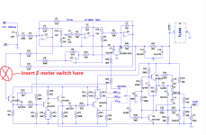
Here is the schematic, I will give a short description, + some oscillograms and pics soon
http://www.diyaudio.com/forums/equipment-tools/207513-simplistic-distortion-meter.html.
Since one of the key functions was the decade amplifier + perfect rectifier, including it in this project was a logical step.
This instrument can of course be built as a stand-alone unit, either with one of the versions of amplifier/rectifier described, or with an alternative solution.
The circuit has been designed in the same spirit as the original THD meter, ie a simple, no-nonsense and effective circuit. It is quite minimalist too, with some "shortcuts" that may look unpalatable, but are logical for this type of gear.
This impedance-meter can display the module and phase of any impedance comprised between 1 ohm (full scale) and 100 ohm. The resolution depends mainly on the indicator. Typically, the usable resolution will be in the 10 milliohm range.
The phase indication follows the +/- degrees convention, 0° being a purely resistive impedance, -90° a purely capacitive one (phase lead), and +90° a purely inductive one (phase lag).
Both the magnitude and phase are formatted to display the value directly: the 1 ohm range corresponds to 1V full scale, and 90° equate to 900mV.
The circuit is designed to be used as a multimeter add-on, but it could as well include its own millivoltmeter.
The circuit is pretty basic, and is not designed for metrological applications: the error range is in the several % range, but it is quite sufficient for hobbyist and workshop applications.
The circuits are based mainly on CMOS used in linear mode, and the performance depend on the exact circuit used, but some compensations are included to minimize effects of the spread. Some selection is advisable for optimum performance.
However, the end result is quite satisfactory, and would be difficult to beat from a performance/cost ratio perspective: my prototype, using non-selected 5% components (at best) achieves a residual phase offset of 0.6° at 1KHz (which remains large compared to the resolution of 0.01°, but in absolute terms, it is rather nice).
It is a very usable and practical instrument, well suited to speakers or amplifiers measurements.
Many improvements are possible, both in range and resolution, but I think the instrument in its current basic form is already quite practical.
Here is the schematic, I will give a short description, + some oscillograms and pics soon
Attachments
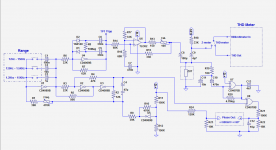
The on-board generator is built around a CD4069. It is an ugly little duckling, but sufficient for the purpose: the impedance-meter is not too demanding on the quality of the waveform, and this solution has the advantages of being simple, cheap, easily tunable and of using a commodity component.
An XR2206 would perform better, but it is obsolete.
To combat the spread inherent to CMOS used in linear, it incorporates a self-compensation based on U5. This way, it will work with any sample of 4069 without adjustment.
C4 holds the correction voltage, it can be in either direction (but will stay the same for a given 4069), which is why a bipolar cap is specified.
One could build the circuit, measure the polarity and use a suitably oriented polar type.
In fact, since the voltage does not exceed a few hundreds mV and the leakage is unimportant, it could even be used in reverse without problem.
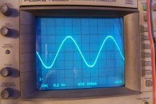
The sinewave is created by U4; it is more like a distorted triangle than a real sinewave (see pic), but it is sufficient.
A V-->I converter (U6) drives the impedance to test with a current of 6.5mA rms (9.25mA peak), which is low enough not to cause troubles with the amplifier or driver to be tested (do not try it on a microphone though).
The resulting voltage is measured by the millivoltmeter section of the THD meter: with the values used, the ranges 1%, 10% and 100% translate neatly into 1Ω, 10Ω and 100Ω full scale.
The voltage developed across the impedance is also sampled by the phasemeter. It is a very crude job, with an XOR gate serving as high gain/low phase shift amplifier/limiter.
Some CD4070B or CD4030B behave quite nicely, others tend to be unstable. Of all the samples tested, only one was completely unusable, it was a NS.
In general, the european types perform better HEFxxxx and HCFxxxx.
It is not difficult to find one that works.
The decoupling and input output capacitors have to be very close to minimize any risk of oscillation.
Note that it would be possible to make something much better: one operator of the 4069 is left, and half of the TLO82 is unused.
With the TLO82 in a x10 preamp, the 4069 as post-amp and the 4030 as a squarer, lower levels would be reachable.
Presently, the limit for a reliable phase indication is Z>0.3Ω.
Using the scheme outlined above, a tenfold improvement would be possible.
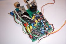
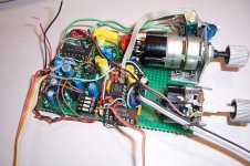
I didn't implement it out of lazyness 😀 and because the board was already very cramped, see pics.
It would also be possible to improve the phase error at high frequencies by using the two spare XOR's with RC's to create a delay exactly matching that of the amplifier.
Anyway, even in the present condition, it already performs quite well.
With the CMOS circuits, the 12V must be clean and stable, as it serves as bias and reference for the circuits.
Since it uses a single supply and a low current, a battery operation is perfectly possible, making floating measurements straightforward.
A simple transformer supply can be made floating too.
An XR2206 would perform better, but it is obsolete.
To combat the spread inherent to CMOS used in linear, it incorporates a self-compensation based on U5. This way, it will work with any sample of 4069 without adjustment.
C4 holds the correction voltage, it can be in either direction (but will stay the same for a given 4069), which is why a bipolar cap is specified.
One could build the circuit, measure the polarity and use a suitably oriented polar type.
In fact, since the voltage does not exceed a few hundreds mV and the leakage is unimportant, it could even be used in reverse without problem.
The sinewave is created by U4; it is more like a distorted triangle than a real sinewave (see pic), but it is sufficient.
A V-->I converter (U6) drives the impedance to test with a current of 6.5mA rms (9.25mA peak), which is low enough not to cause troubles with the amplifier or driver to be tested (do not try it on a microphone though).
The resulting voltage is measured by the millivoltmeter section of the THD meter: with the values used, the ranges 1%, 10% and 100% translate neatly into 1Ω, 10Ω and 100Ω full scale.
The voltage developed across the impedance is also sampled by the phasemeter. It is a very crude job, with an XOR gate serving as high gain/low phase shift amplifier/limiter.
Some CD4070B or CD4030B behave quite nicely, others tend to be unstable. Of all the samples tested, only one was completely unusable, it was a NS.
In general, the european types perform better HEFxxxx and HCFxxxx.
It is not difficult to find one that works.
The decoupling and input output capacitors have to be very close to minimize any risk of oscillation.
Note that it would be possible to make something much better: one operator of the 4069 is left, and half of the TLO82 is unused.
With the TLO82 in a x10 preamp, the 4069 as post-amp and the 4030 as a squarer, lower levels would be reachable.
Presently, the limit for a reliable phase indication is Z>0.3Ω.
Using the scheme outlined above, a tenfold improvement would be possible.
I didn't implement it out of lazyness 😀 and because the board was already very cramped, see pics.
It would also be possible to improve the phase error at high frequencies by using the two spare XOR's with RC's to create a delay exactly matching that of the amplifier.
Anyway, even in the present condition, it already performs quite well.
With the CMOS circuits, the 12V must be clean and stable, as it serves as bias and reference for the circuits.
Since it uses a single supply and a low current, a battery operation is perfectly possible, making floating measurements straightforward.
A simple transformer supply can be made floating too.
Attachments
- Status
- Not open for further replies.