Hi,
I'm posting this here because my system is built around a Modulus-86, and the build thread for that particular amp is in this forum section if anyone feels that it's in the wrong place feel free to move it.
I should start out by saying I'm incredibly happy with my system, its a fairly modest set up built around accuracy and transparency (hence me building a modulus-86 last year), so it's not that I'm not satisfied with the system, I'm just curious about how impedance matching may (or may not) have an impact on my system.
If I get the ball rolling with an overview of my system, I'll try to include the input and output impedance of each device in the chain, then hopefully people could explain to me if and why there may be anything that could adversely affect the performance of the system.
My primary music source is a hi quality streaming service running on a laptop, the DAC connected to the laptop is a JDS Labs O-Dac Rev B. I cant find the specific output impedance but looking at the specs i found this "Maximum Output Line Out 100K - 2.1 VRMS"
The DAC goes through a passive preamp which I use for switching between 2 sources and controlling the volume of the output. It's a Schiit SYS, according to their specs it has an input impedance of 10K ohms, and the output impedance is 5K Ohms MAX (I'm assuming they state the MAX because this dependent on where the potentiometer is set - which is what I'm really interested in)
The output of the passive pre then goes into my Adam T10S powered subwoofer. The sub has a crossover which I set at 85Hz and passes everything above to the madulus-86. I'm not a huge sub bass person, I just have it on quite low just to offer a subtle floor of sub and take a bit of duty off my speakers, so they can shine in the range they do best.
Heres where it get tricky though, as we dont have any impedance ratings for the input and output on their specs ADAM Audio - T10S Active Subwoofer For T Series Studio Monitors
From there the high passed signal goes to the modulus-86 amp, although tom's site doesnt specifically state the input impedance it states the input sensitivity 1.8 V RMS 40 W, 8 Ω
Finally, the amp is powering a pair of Magnepan LRS (Fantastic speakers by the way, they deliver that "in the room and invisible" performance that want from music) They are rated at 4 Ohms, which i know the amp has no problem dealing with (even less so now I've added the sub, the amp doesnt really get more than just warm)
So, I know thats quite a lot to digest, so if you got this far, thanks for reading.
I guess the main thing I'm intrigued about is the passive pre amp and if the potentiometer will make an audible difference if I'm setting it as half way (50% attenuation ?)
Thanks again.
Tom
Last edited:
I guess the main thing I'm intrigued about is the passive pre amp and if the potentiometer will make an audible difference if I'm setting it as half way (50% attenuation ?
This is the bane of "passive pre-amps." No op-amps = no distortion is the dogma; but in fact passive pre-amps can introduce plenty of distortion.
If your power amp has an RF input trap (I'm almost sure the Modulus-86 has one), then the input impedance can alter its turnover frequency. Specifically, it can lower it. Since turnover frequencies are typically 159 kHz to 200 kHz, there's not much room for error.
Here's an example. Suppose the trap uses a 1K series resistor, with a turnover frequency of 159 kHz. Your maximum output impedance is 5 Kohms as claimed. This will reduce the turnover frequency to around 30 kHz! This is obviously way too low and will likely be audible to some people. In fact the turnover frequency will vary between 30 and 159 kHz with the potentiometer setting.
Solution? Buffer the volume control with an op amp on its output. Output impedance of op amp circuit = 47 to 100 ohm, set with a series resistor. This will have a negligible effect on the RF trap's turnover frequency.
What makes you think the several designers didn't consider the question?
Modern audio "has to be mix-and-match". Salesmen can rarely sell a whole system, most sales are pieces which must play well with the customer's other pieces.
This generally means outputs <1k and inputs >10k.
That passive volume control is the obvious odd man out. And it drives a box with little useful specification. If you were a DIY person you could (as Eddie says) build a unity gain buffer (couple bucks) and see if it makes any difference.
The highest output impedance I have to deal with is my external sound card, a Behringer unit with an output impedance of 400 ohms. This has negligible practical effect in the "mix and match" world.
Every line level circuit I build has 47K input impedance and 47 ohm out impedance where it interfaces with the outside world. That will work with any modern equipment.
Every line level circuit I build has 47K input impedance and 47 ohm out impedance where it interfaces with the outside world. That will work with any modern equipment.
Tom-the-Modulus-designer has a thread for building his Modulus-86 amp, so you can probably just ask him there what the input impedance is. You might even direct him to this thread, from what I've seen he's been very helpful with those who have built his amps.From there the high passed signal goes to the modulus-86 amp, although tom's site doesnt specifically state the input impedance it states the input sensitivity 1.8 V RMS 40 W, 8 Ω
But as others said, if there's anything limiting your system, it would surely be that passive volume control.
....modulus-86 amp, although tom's site doesnt specifically state the input impedance...
Site:
Modulus-86: DIY 65W power amplifier achieving -120dB (0.0001%) THD – Neurochrome
"...input to the composite amplifier is provided by a THAT1200 differential receiver...."
This is a commercial part by a known company. Sheet:
http://www.thatcorp.com/datashts/THAT_1200-Series_Datasheet.pdf
"...Input Impedance ZIN-DIFF Differential 48.0 kΩ..."
Yep. 48 kΩ input impedance on the MOD86. It'll deliver 65 W into 4 Ω or 40 W into 8 Ω.
Impedance matching is not relevant for audio. What matters in audio is that the output impedance should be low (say < 100 Ω) and the input impedance should be high (10-100 kΩ).
A "passive preamp" (aka volume control) has a high output impedance. At the worst case setting, it's R/2, where R is the total resistance of the volume pot. The input impedance of the "passive preamp" is R.
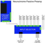
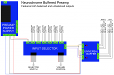
I prefer a buffered preamp where the volume control is connected to the input of the preamp and the output from the volume control is taken to a buffer. That gives you high input impedance (I'd choose a 10 kΩ pot) and low output impedance (< 1 Ω for a typical solid-state buffer). I've attached an example of such a preamp.
Tom
Impedance matching is not relevant for audio. What matters in audio is that the output impedance should be low (say < 100 Ω) and the input impedance should be high (10-100 kΩ).
A "passive preamp" (aka volume control) has a high output impedance. At the worst case setting, it's R/2, where R is the total resistance of the volume pot. The input impedance of the "passive preamp" is R.
I prefer a buffered preamp where the volume control is connected to the input of the preamp and the output from the volume control is taken to a buffer. That gives you high input impedance (I'd choose a 10 kΩ pot) and low output impedance (< 1 Ω for a typical solid-state buffer). I've attached an example of such a preamp.
Tom
Attachments
Last edited:
What's the input capacitance? What's the RF trap f3? What size resistor is used in the trap? These are the parameters we need to know to figure out if a passive volume control can be placed at the input.
This is a lesson I learned in high school. I built a tube power amplifier. It was "modern" with 47K input and low noise transistorized power supply. It had an input RF trap I copied from somewhere (I wasn't clear on everything in high school, just lucky.) I was driving it with a modern, op amp based preamp (CA3140 if you must know) with a low output impedance. It worked fantastic. Then my neighbor brought over his tube preamp. This preamp (1950s technology) did not drive my power amp very well, although his 1950s era hi fi worked very well with this preamp. All the highs were gone when we tried to drive my power amp. It took me a while (like a year) to figure out why but I never forgot.
I'm with you Tom when it comes to using buffers. They make any volume control work better. I build small boards for my projects with Alps Blue Velvet and an op amp right on the board. You can drive a cable directly from this board, no worries.
What's the input capacitance? What's the RF trap f3? What size resistor is used in the trap? These are the parameters we need to know to figure out if a passive volume control can be placed at the input.
For the MOD86, you're looking at 50-100 pF, differential. The -3 dB cutoff for the RF input filter is in the high 100s of kHz to low MHz if I recall correctly. It's significantly higher than the -3 dB frequency of the MOD86 itself (~85 kHz), which is set by the not-so-optional stability components around the LM3886.
Tom
Considering the SYS is just a 10K pot and a switch, shouldn't the max output impedance rather be 2.5K (R/4) ?t's a Schiit SYS, according to their specs it has an input impedance of 10K ohms, and the output impedance is 5K Ohms MAX (I'm assuming they state the MAX because this dependent on where the potentiometer is set - which is what I'm really interested in)
At the worst case setting, it's R/2, where R is the total resistance of the volume pot.
Tom
Tom, should that not be 1/4*R? In the mid position, looking into that wiper, you see 1/2*R parallel to 1/2*R.
Jan
Considering the SYS is just a 10K pot and a switch, shouldn't the max output impedance rather be 2.5K (R/4) ?
Is the "10k pot" a proven fact?
But FWIW, these ARE the numbers published by SCHIIT Audio:
"Input impedance: 10k ohms
Output Impedance: 5k ohms maximum"
(also cited in #1 above)
I can't make it work out to those numbers. If low-Z source it should approach Z/4 at -6dB. If hi-Z source (Eddie's neighbor' tube preamp) it should approach 10k full-up. A 10k source makes it meet specs but is very odd, also if the specs require careful external conditions that should be in the fine print. I suspect someone asked, someone blurted "5k!", and nobody checked the answer.
By my math, a 30 foot cable driven by 2.5k worst-case will be about -3dB@64kHz, -1dB@32kHz, so -0.5dB@16kHz. To my ears this is insignificant; a less-damaged listener may notice the slight difference.
Сould you give me a possibility to correct this statement? With actual nowadays opamps I would rather say: "...and the input impedance should be high (0.6-10 kΩ)."Impedance matching is not relevant for audio. What matters in audio is that the output impedance should be low (say < 100 Ω) and the input impedance should be high (10-100 kΩ).

I even heard (in russian DIY-audio 'high-end' segment) some people used something like 50-100 R potentiometers - and they were happy! despite of they knew (and heard) a bit higher distortion.
Last edited:
If the system is *designed* for low-Z, you can do anything you like. See most telephone and broadcast networks: 150, 200, 600, or 900 Ohms.
But ask the usual 19-cent chip to drive 150 Ohms at high level, it will strain or clip.
It is generally accepted that most home and studio interfacing is>=10K input.
There is normally NO objection to much higher loads, even 1Meg.
________ OTOH.....
It is possible to invert the situation. Define output *current*. Adjust input impedance to get a convenient voltage. DIN had a hi-fi interface like this. I only saw it for a few years/decades, but it was not for any technical flaw that it faded away.
Tom, should that not be 1/4*R? In the mid position, looking into that wiper, you see 1/2*R parallel to 1/2*R.
Ah! You're right. R/4. Good catch. So 2.5 kΩ for a 10 kΩ pot, which is still pretty darn high. Granted that is the worst case output impedance.
Tom
I even heard (in russian DIY-audio 'high-end' segment) some people used something like 50-100 R potentiometers - and they were happy! despite of they knew (and heard) a bit higher distortion.
Good luck finding an opamp (or any other small-signal circuit) that will drive a 50-100 Ω pot with low distortion. Finding a volume pot that can handle the dissipated power could be a challenge as well. But then again, low distortion is often not a goal within the audiophile or 'high-end' community.
That's not to say you can't build a circuit like that. Just build a headphone amp to drive your volume pot... 🙂
Tom
There is normally NO objection to much higher loads, even 1Meg.
One noteworthy exception is the volume pot. A 1 MΩ pot would definitely raise the noise floor of the amp/preamp considerably. In many of my designs, the 10 kΩ volume pot is the dominant noise source. I'm using a 5 kΩ custom ALPS pot in my TCA HPA-1 for that reason.
But as an input impedance in general, 1 MΩ is fine. Recall, it'll be in parallel with the source's output impedance once the source is connected. The output impedance will "win" and the total impedance of the input node becomes, practically, the output impedance of the source.
Tom
Firstly thanks to everyone who has replied, I'm pleased that my curiosity sparked an interesting thread (and helped me learn a few things)
Also Tom, thanks for commenting, a buffered pre could be a fun little xmas build project. and thanks again for all the guidance building your amp last year, I'm still floored by it every time I hear it. (And yes it can drive Magnepans effortlessly)
At the risk of sparking more debate, but I may as well while I have you here.
Could a better solution be to insert a volume pot somewhere in the modulus-86? Is there a fixed value resistor in the circuit which could be replaced with a variable one that would adjust the gain ratio of the amplifier (its 1:20 as standard IIRC?)
Or is this not good practice due to additional noise or some other instability a variable resistor may introduce?
Thanks again
Tom
Yep. 48 kΩ input impedance on the MOD86. It'll deliver 65 W into 4 Ω or 40 W into 8 Ω.
Impedance matching is not relevant for audio. What matters in audio is that the output impedance should be low (say < 100 Ω) and the input impedance should be high (10-100 kΩ).
A "passive preamp" (aka volume control) has a high output impedance. At the worst case setting, it's R/2, where R is the total resistance of the volume pot. The input impedance of the "passive preamp" is R.
I prefer a buffered preamp where the volume control is connected to the input of the preamp and the output from the volume control is taken to a buffer. That gives you high input impedance (I'd choose a 10 kΩ pot) and low output impedance (< 1 Ω for a typical solid-state buffer). I've attached an example of such a preamp.
Tom
- Home
- Amplifiers
- Chip Amps
- Impedance matching