SY, I'm detecting definite sibilance with my set-up, Definite "Tsss" when I should be getting "S".
If you recall I'm not using the input transformers.
I'm driving B1 into Impasse and then into F5 and then onto B&W 683's.
B1 into Aleph4 into B&Ws is clear and clean.
If you recall I'm not using the input transformers.
I'm driving B1 into Impasse and then into F5 and then onto B&W 683's.
B1 into Aleph4 into B&Ws is clear and clean.
In post #659 http://www.diyaudio.com/forums/pass-labs/136835-impasse-preamplifier-66.html#post3671144 I indicated problems with certain music passages involving sharp transients.
My initial Impasse build had rather high distortion in the right channel, which I could not explain, and I didn't do the right measurements to isolate the problem. Spice simulations suggested that I might be able to reduce the distortion by adjusting Vgk of the triodes. I removed the LEDs from the cathodes of the 6SN7 triodes and installed a 680ohm resistor paralleled with a potentiometer to adjust the Vgk of the triodes, and adjusted the pots for minimum THD. Unfortunately, I did not record any voltage measurements after those adjustments. After listening to the Impasse into my F4 for several weeks I was not happy with the sounds of certain music passages involving sharp transients. I put the Impasse preamp aside until recently when I decided to do more a thorough examination of the voltages in my Impasse.
Since I had not build anything with vacuum tubes for 50 years, I read Morgan Jones "Valve Amplifiers" book to get better up to speed on vacuum tube circuits. I now understand the problem. In minimizing THD, A had adjusted Vgk of the left channel (without measuring it) to less than 1 Volt, causing grid current at levels higher than 4 Volt peak output.
Today I readjusted the pots for "nominal" Vgk voltages of 3.5V and made measurements of voltages which are shown below. The two Electro-Harmonix 6SN7 triodes are grossly mismatched. Both 6SN7 triode CCSes were adjusted for 8ma current (0.096V drop across 12.0K resistors). As you can see, the left channel H2 isn't too bad at Vgk = 3.5V. but the the right channel is crappy.
Left Channel
Vgk = 3.5V Vp = 191v
H1 -27dB
H2 -109dB .008%
H3 -123dB .0016%
Right Channel
Vgk = 3.5V Vp = 142V - close to Tung-Sol 6SN7GTB datasheet
H1 -27dB
H2 -98dB .028% -- CRAP
H3 unmeasurable
I carefully adjusted to cathode resistor pots for minimum THD and got the following measurements which aren't too bad, but clearly the triodes are seriously mismatched. Here are the new measurements:
Left Channel
Vgk = 3.24V Vp = 192V
H1 -27dB
H2 -115dB .004%
H3 -133dB .0005% near noise floor
0.5mV AC noise measured with Fluke with input shorted
Right Channel
Vgk = 5.71V Vp = 192V
H1 -27dB
H2 -119dB .0025%
H3 -130dB .0007% near noise floor
0.8mV AC noise measured with Fluke with input shorted
I have been listening to the Impasse as adjusted for minimum THD and it now sounds good. I have not been able to detect problems of the type I heard earlier.
I probably should purchase one or more additional 6SN7 tubes in an attempt to find tubes with better matched halves. Any recommendations for brands or sources?
Simulations suggest that another way to adjust H2 is to modify R8, the top resistor of the voltage divider driving the cathode follower, while retaining the 3.5V LED cathode bias circuit. Any opinions?
Order of probability:
1. Bad tube.
2. Bad solder joint somewhere.
3. Bad component.
I've run 5692 (RCA) and CV1988 for the 6SN7. I briefly used an EH 6SN7 for a unit I was troubleshooting and it seemed to be quite good. Sample of one, so take that with a boulder of salt.
1. Bad tube.
2. Bad solder joint somewhere.
3. Bad component.
I've run 5692 (RCA) and CV1988 for the 6SN7. I briefly used an EH 6SN7 for a unit I was troubleshooting and it seemed to be quite good. Sample of one, so take that with a boulder of salt.
I ordered a Tung-Sol 6SN7 with matched triodes today. I will give that a try.
How about the issue of "sweet-spot" tuning: Vgk vs. the 2nd stage bias voltage (ie. R8/R9 resistor network) vs. CCS current (nominally 8mA)?
How about the issue of "sweet-spot" tuning: Vgk vs. the 2nd stage bias voltage (ie. R8/R9 resistor network) vs. CCS current (nominally 8mA)?
That's probably very second order. I've built two, did plug and play with several tubes and no adjustments, and distortion was low in every case. Perhaps with individual tuning I could drop it from (say) 0.05% to 0.03%, but it's already way below any reasonable threshold of audibility.
The B1 is simply acting as a volume control and I'm also not using the input transformers.
I've got the PSU stabilised now, it looks as though some of the DIY PCB traces were a bit "thin" so I've doubled them up with solid wire and all seems well in that department.
My 6SN7 are actually marked 6N8S ??
I've got the PSU stabilised now, it looks as though some of the DIY PCB traces were a bit "thin" so I've doubled them up with solid wire and all seems well in that department.
My 6SN7 are actually marked 6N8S ??
Check the soldering around the regulator and its feedback resistors.
Hi Sy, you were probably right, please see post above.
Due to the lower voltage of the mains transformer I've had to parallel C101 with another 100uF which now enables the regulator to output 350V as designed.
Still got this sibilance issue though.
I've just ordered one of these to see if it makes any difference.
https://www.hotroxuk.com/catalogsearch/result/?q=6SN7EH
https://www.hotroxuk.com/catalogsearch/result/?q=6SN7EH
I've just switched input sources to my CD and the silbilance has gone. looks like it might just be on the FM reception.
R1
Just to be sure - R1 value should be 18k for Jensen? SY mentioned 15k in the article text, but 18k in the BOM...
Dave, sorry, I didn't see your previous post. You want the parallel combination of the resistor and the potentiometer to be about 10k. If it's not exactly, no tragedy. But 10k is the optimal load for the Jensen. For the Cinemag, you want the parallel combo to be 15k.
Just to be sure - R1 value should be 18k for Jensen? SY mentioned 15k in the article text, but 18k in the BOM...
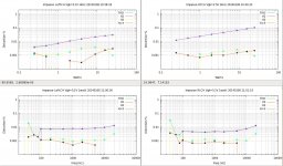
I finally found the cause of the anomalous Vgk readings on my Electro-Harmonix 6SN7. I was getting Vgk=3.5V on one triode and Vgk=5.7V on the other triode at the distortion "sweet-spot". The problem was a DUMB mistake on my part. My cathode voltage test point on one triode was not at the cathode, but on the bottom of the 300R resistor connected to ground thru a 500R pot. Thus, at 8mA the cathode voltage measurements for that triode were 2.4V low.
Corrected my test point, I found a very nice "sweet-spot" at Vgk=5.1V on each triode. Below are distortion sweeps for each channel. (Note that the legend for the RtCh watt-sweep is in error: Vgk was 5.1V, not 3.5V). Measures well and sounds great! I just checked and found that 3X of my LEDs in series drop 5.4V at 8mA, so I will rerun the sweeps at Vgk=5.4V.
Corrected my test point, I found a very nice "sweet-spot" at Vgk=5.1V on each triode. Below are distortion sweeps for each channel. (Note that the legend for the RtCh watt-sweep is in error: Vgk was 5.1V, not 3.5V). Measures well and sounds great! I just checked and found that 3X of my LEDs in series drop 5.4V at 8mA, so I will rerun the sweeps at Vgk=5.4V.
Attachments
Last edited:
Just to be sure - R1 value should be 18k for Jensen? SY mentioned 15k in the article text, but 18k in the BOM...
It won't make too much difference. You just want the parallel combo with the volume control to be about 10k. The tolerance here is pretty broad.
It won't make too much difference. You just want the parallel combo with the volume control to be about 10k. The tolerance here is pretty broad.
OK, thanks. 15k || 100k gives 13k, which is a bit closer to 10k than 18k || 100k = 15k.
If I want to use a stepped attenuator I suppose it should be either series type or ladder type as they have constant input impedance (like a potentiometer). Shunt type attenuator impedance vary depending on the position so it is no good for the input transformer. Am I right?
In theory, that can reduce noise from the HV rectifiers. If the preamp is dead quiet, that advantage may be moot...
- Home
- Amplifiers
- Pass Labs
- ImPasse Preamplifier