Hey everyone,
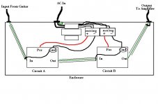
I am an avid learner of electronics. I play guitar and am currently building an analog effects processor that I'll run my guitar's signal through and onto my guitar tube amp. This floor unit contains about 10 analog circuits, two transformers, each with many secondaries to power each of the circuits individually to isolate and eliminate ground loops (I think this isn't too far off from tube amp building so I figured this would be a good place to post). I am now wiring the circuits into the enclosure (a bent aluminum box) and need to know the best way to shield this beast. Because the power transformers will be contained inside the enclosure along with the sensitive audio circuits, I want to shield EVERYTHING as a first step. Does this diagram look proper to you? The in/out jacks are not isolated from the enclosure, fyi.
My thinking is to shield the inputs of each circuit in the chain. So I ground the input wire shield only at one end, in this case the PCB end and leave the other end floating. At the end of the chain, I guess that means I should ground the shield at the output jack then? Everyone says grounding should be so straightforward, but it really isn't clear to me yet exactly how this stuff works. I need an animated diagram or something to drill it into my head! What say you guys?
Attachments
HI
in a word no ,you dont have a good circuit for the signal to flow around .Can you answer ......are you using a different voltage on each board and to clarify these are/is single voltage supplies ( not +15/-15) ? , have the boards got a connection point on the inputs and ouputs to connect the screens to,is the circled GROUND on the boards only connected to the negative,and finally your using uninsulated 1/4 inch jacks on i/p and o/p.
in a word no ,you dont have a good circuit for the signal to flow around .Can you answer ......are you using a different voltage on each board and to clarify these are/is single voltage supplies ( not +15/-15) ? , have the boards got a connection point on the inputs and ouputs to connect the screens to,is the circled GROUND on the boards only connected to the negative,and finally your using uninsulated 1/4 inch jacks on i/p and o/p.
HI
in a word no ,you dont have a good circuit for the signal to flow around .Can you answer ......are you using a different voltage on each board and to clarify these are/is single voltage supplies ( not +15/-15) ? , have the boards got a connection point on the inputs and ouputs to connect the screens to,is the circled GROUND on the boards only connected to the negative,and finally your using uninsulated 1/4 inch jacks on i/p and o/p.
Hello!
The majority of the boards will use negative Gnd and +9vdc, one board will have +12vdc, and one board will use positive Gnd and -18vdc.
As the diagram shows, I only connect one end of the screen to the Gnd on the PCB. So the screen from the input jack to circuit A is grounded at circuit A's PCB. The screen from the out of circuit A to the in of circuit B is grounded at circuit B's PCB. The screen from the out of circuit B is then grounded to the output jack. All jacks are uninsulated. The grounds connect to the negative on negative ground circuits and the positive on positive ground circuits. I'm thinking maybe I should insulate all jacks, then ground the output jack to the chassis at the same point that I tie the AC safety to.
Check the one that uses +12V DC, if you have a schematic - you might be able to get away with running it on +9V.
Hi
are these home made boards and are they going to be daisy chained .The positive ground board (unusual) will need its own isolated secondary with rect/reg etc.I am getting to the grounding ,but the schematic makes your build look more simple than it actuallly will be.
are these home made boards and are they going to be daisy chained .The positive ground board (unusual) will need its own isolated secondary with rect/reg etc.I am getting to the grounding ,but the schematic makes your build look more simple than it actuallly will be.
Check the one that uses +12V DC, if you have a schematic - you might be able to get away with running it on +9V.
That particular circuit has an onboard 12v regulator and uses delay IC chips that require that voltage.
Hi
are these home made boards and are they going to be daisy chained .The positive ground board (unusual) will need its own isolated secondary with rect/reg etc.I am getting to the grounding ,but the schematic makes your build look more simple than it actuallly will be.
These boards are homemade using verified schematics and are working correctly too. Yes, one of them is an unusual positive ground circuit. Each of my ten circuits will get a dedicated and isolated secondary from the transformers. I made the diagram simplified instead of drawing out all ten circuits as the idea applies to two circuits as it does ten.
Thanks for the help guys, this project is consuming ALL my efforts currently!
Connect the screen at the i/p jack
connect the screen at the o/p jack
connect the screen at the i/p rail you are calling ground on each board
connect the screen at the o/p rail you are calling ground on each board
Keep the uninsulated jacks as these now connect your screens to the chassis and thus to the mains earth and thence to ground .The circuit as a whole will now be grounded at both the i/p jack and o/p jack but this wont matter as you have a big lump of chassis metal connecting the 2......no need to reply.
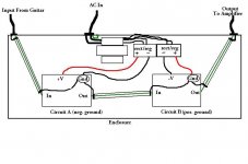
I will reply anyway. Thank you, Epicyclic. As relative novice, I must confirm whether or not I understand your directions. Is this updated diagram correct then?
**I also changed Circuit B to reflect the example of my one positive ground circuit as well. Something about that positive ground and negative ground together scares me...
**I also changed Circuit B to reflect the example of my one positive ground circuit as well. Something about that positive ground and negative ground together scares me...
Attachments
Yes thats what i typed. Peviously wasnt trying to offend home made is good ,thats diy.
+ ground answer....when you connect a transformer to the mains (and the secondary is isolated) you float the secondary .You can connect either leg to ground,but obviously not both .BEWARE of AUTO TRANSFORMERS the secondary is NOT isolated .Then provided the -ve 18V has its own dedicated(insulated from others) secondary you wont have a problem.Look at it this way when you connect 2 pieces of equipment together you are not aware wether they have grounded the +ve or -ve .Naturally they have their own isolated secondary.
+ ground answer....when you connect a transformer to the mains (and the secondary is isolated) you float the secondary .You can connect either leg to ground,but obviously not both .BEWARE of AUTO TRANSFORMERS the secondary is NOT isolated .Then provided the -ve 18V has its own dedicated(insulated from others) secondary you wont have a problem.Look at it this way when you connect 2 pieces of equipment together you are not aware wether they have grounded the +ve or -ve .Naturally they have their own isolated secondary.
Last edited:
No offense taken, epicyclic. I just wanted to affirm that the diy circuits were built properly as should be so as not to confuse the situation. I really appreciate you taking the time to answer my specific questions.
I had an idea about positive and negative grounded circuits for that very reason of hooking up random devices and not knowing what they used. Thanks for cementing that in my mind. Thanks again!
I had an idea about positive and negative grounded circuits for that very reason of hooking up random devices and not knowing what they used. Thanks for cementing that in my mind. Thanks again!
- Status
- Not open for further replies.
- Home
- Live Sound
- Instruments and Amps
- I'm new here. Question about grounding in an analog multicircuit processor for guitar