I posted this on the Power Supplies section but got no responses so I'm trying here
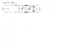
I rescued a Schaffner IEC inlet filter from an ADAT M/C before I sent it to scrap. It's the FN 9246 High performance IEC inlet filter I have from here: http://www.schaffner.com/components/en/product/productL22.asp?level=3 This unit has a 470K ohm resistor between L & N.
I put it on the inlet of a tube amp that I'm rebuiling. This amp has a switch and before using it I tested the power to ensure that all is OK.
I'm getting a voltage accross L & N with this switch turned to off. Do I need a dual gang switch instead or put a single pole switch before the inlet?
It's not clear how you have wired this or exactly where voltage is appearing. Can you draw a diagram or explain a bit better?
Not good with the drawing of circuits so I'll try to draw a word picture:
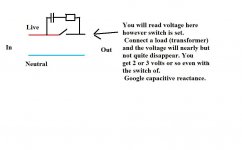
All I've done is replace a normal IEC inlet with a filtered one and now when I measure accross the Neutral & Live wires inside the amp that connect to the trafo I see voltage there even though amp power switch is off.
I've since googled IEC inlet filters & see that they either use a dual gang switch after the filter or a single pole switch before the filter. I wasn't aware about these issues before.
Have others experienced this before?
Just draw it !! 🙄 You are probably reading through some caps or something. A 0.1mfd across a switch will show voltage on the switched side with no load connected but there is no "current capability" with it. See how hard it is to explain without pictures 🙂
No luck, only got MS Works. --- Wordpad and notepad. Can read the text, thats all 🙂 . My computer skills aren't that hot.
From what you say it sounds like you may be reading through caps etc. You say you have 228 volts was it on the tranny primary. But the amp is not powered ? like this. With 228 volts across the primary the amp has to be "on". If it isn't it's to do with where you are measuring from or the position in the circuit of the switch.
It's hard to say without seeing it, wait and see what Richie says.
Sorry 🙂
Hi Mooly, just to expand your world a little, through google documents, you can work with and share normal office files at no cost.
Or OpenOffice which is free and works fine with all the MS Office files I've tried.
The HTML file is missing the image file.
I think the issue is the cap across the power switch leaking tiny current causing a voltage to be read by a high impedance digital meter. The same effect should happen with a normal inlet.
However, thinking about it again, the low impedance of the transformer should stop this happening. If the unit is not actually on and working when you are measuring this voltage then I suggest you may be measuring wrong or have a faulty meter.
Filtered inlets usually use a switch before simply to save the filter being always across the mains and being a fire hazard.
Is the transformer actually connected when you are getting these strange readings? (ref para 4 in my last post)
Sounds like leakage current. The FN-9246 series is rated with
373uA to 797uA leakage (depends on size of filter) if you don't
have one of the medical rated ones (FN-9246B series) which
are rated for only 2uA leakage. I doubt that the salvaged model
is one of the B series devices?
373uA to 797uA leakage (depends on size of filter) if you don't
have one of the medical rated ones (FN-9246B series) which
are rated for only 2uA leakage. I doubt that the salvaged model
is one of the B series devices?
Aha, it turns out that the tap on the tranformer I was connecting L to was just a dummy tap (not connected to anything). Whit transformer properly connected up the voltage is correctly reading zero when switched off.
So just to clarify for my understanding: without any load the N & L will read nearly full voltage accross them but at very low current due to the cap accross the switch?
Thanks guys!
So just to clarify for my understanding: without any load the N & L will read nearly full voltage accross them but at very low current due to the cap accross the switch?
Thanks guys!
Thanks Nordic & Richie.
Strange old world, as I was typing reply earlier Java update flashed up in system tray. Update includes Open Office if needed.
Good to hear JKennys problem is sorted too.
Thanks guys.
Strange old world, as I was typing reply earlier Java update flashed up in system tray. Update includes Open Office if needed.
Good to hear JKennys problem is sorted too.
Thanks guys.
- Status
- Not open for further replies.
- Home
- Amplifiers
- Solid State
- IEC Inlet filter issue