Hello,
I'm looking for the idling current of the final stage of the Rega's amplifiers Mira (it's the same final stage for Mira1, 2 and 3).
If anybody has a Mira and can juste give me the tension on the two big white emitter resistors it would be very nice.
Thank's.
EG
I'm looking for the idling current of the final stage of the Rega's amplifiers Mira (it's the same final stage for Mira1, 2 and 3).
If anybody has a Mira and can juste give me the tension on the two big white emitter resistors it would be very nice.
Thank's.
EG
It should probably be about 20mA, and if your R5,6,7 and 8 are 0.22 ohm, then the voltage would be 4.4 mV; 5mV would give 23mA.
Out of interest, what value did you settle on?
Out of interest, what value did you settle on?
Hello,
Thanks a lot for your answer!
R are 0,22ohm, I ajust the voltage at 4,4mV after 1 hour, and it's still at this value after 2 hours.
In fact there was a problem on one chanel, and I had to change the two Power Transistors. But I was not sure that the biais of the other channel was good, in fact it was (4,4mV).
Do you have a Mira? Which model?
Mira
Sorry for the late posting.
I do have a Mira - a clamshell, the main PCB says "ver 2" so I assume it's a Mk II. tested in 1998. I bought it after my last post.
It has an electromechanical rotary switch for remote control input switching - works OK, but they forgot to add muting circuitry to silence the inputs you're passing over.
When I got it one channel ran very hot - the 'OK' channel was biased at 7ma, so I set the hot channel to that, and it has worked OK.
Last edited:
Just heard from a guy who works at Rega that the bias should be 2.5 mv (across the 0.22 ohm emitter resistors) so about 11 ma it seems!
Info for Clamshell Maia (Mira minus the preamp) from Rega:
Setting up the Maia’s Quiescent Current.
Before any changes can be made, please make sure the amplifier is “cold”, ambient temperature of 20º C - 25º C and switched off!
Equipment:
1x Mutli-meter (DVM)
1x Trimmer
2x Crocodile clips.
Open the lid of the Maia, and locate the potentiometers in the power stage, turn them fully anti-clockwise and then adjust according to the following procedure.
Turn on the amp and wait for the relay to click over.
Attach the crocodile clips to the right hand output resistors on test points TP1 and TP3.
Switch DVM to read mV’s, it should be reading nothing! Then turn potentiometer until the DVM reads 2.5mV tolerance of +/- 0.1mV. - Don’t take too long doing this as the left side amp is starting to warm up too!
Now attach the crocodile clips to the left hand output resistors on test points TP4 and TP6.
Then turn left hand potentiometer until the DVM reads 2.5mV tolerance of +/- 0.1mV.
Now leave amp on for 15 minutes to stabilise.
Check the voltages on both channels, they should read between 6.5mV – 7.5mV, if they don’t then re-adjust to correct voltage. – This reading is dependant on ambient temperature so may vary!
Leave amp for another 5 minutes to stabilise if adjusted then recheck voltages again.
If all is ok then replace the lid and panels.
Hello,
Thank you. But the think important for me was the voltage, I know very well how to mesure the bias across emitter resistors.
Any way this amplifier has been sold.
Best regards.
2N6658
Thank you. But the think important for me was the voltage, I know very well how to mesure the bias across emitter resistors.
Any way this amplifier has been sold.
Best regards.
2N6658
Thank you. But the think important for me was the voltage, I know very well how to mesure the bias across emitter resistors.
Any way this amplifier has been sold.
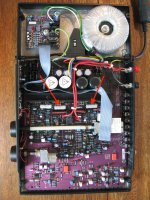
Mashley_nad has kindly been assisting me (by PM) in running the test and adjustment procedure covered in this thread. I asked for clarification, which is why the picture has been added here. I realize it's an old thread, however the information is very useful to other owners of this equipment, and if you look around online, there is very little if any similar information available for this model. As well as that, where people working on other amplifiers and audio equipment often have the service manual to work with, that's not the case with Rega units.
Last edited:
Hi
I recently offered to investigate a faulty Rega Mira amplifier for some friends. I found that one of the A1386 output transistor in one channel had gone open circuit and taken several other devices with it. I repaired the damaged semiconductors (reputable suppliers only) and replaced the complementary C3519 but find that I am unable to set the correct bias for this channel. Adjusting the trimmer only increases the output current slightly. As far as I can tell voltage measurements of this channel match the other closely, though the physical layout of the channels is very different and the board numbering does not match the circuit diagram (see earlier in the thread), making this more challenging, and I may have missed something. In situ junction voltage drops seem to show no further defective transistors or diodes, at least when the circuit is not powered. Despite this I eventually replaced all semiconductors in the channel to no avail.
For the last 20 years or so I've been a valve man and my solid-state skills are little rusty! All I can think of is that I used BD139–16 and BD140–16 devices in place of the originals BD139 and BD 140- ok I thought, but was I correct?
Any help gratefully received
Paul N
Hi
Has any one any ideas?
Moderators- would I be better to start a new thread “Problem repairing Rega Mira amplifier” and attach the schematic from this thread directly?
Thanks
PaulN
Has any one any ideas?
Moderators- would I be better to start a new thread “Problem repairing Rega Mira amplifier” and attach the schematic from this thread directly?
Thanks
PaulN
Hi
I just realised that the schematic I mentioned was on a different thread! I've now attached it. Though I noticed that in the actual amp the string of diodes numbers three, not four as drawn. The amp is a version 4, completed in 2002.
Thanks
Paul N
Hi
I recently offered to investigate a faulty Rega Mira amplifier for some friends. I found that one of the A1386 output transistor in one channel had gone open circuit and taken several other devices with it. I repaired the damaged semiconductors (reputable suppliers only) and replaced the complementary C3519 but find that I am unable to set the correct bias for this channel. Adjusting the trimmer only increases the output current slightly. As far as I can tell voltage measurements of this channel match the other closely, though the physical layout of the channels is very different and the board numbering does not match the circuit diagram (see earlier in the thread), making this more challenging, and I may have missed something. In situ junction voltage drops seem to show no further defective transistors or diodes, at least when the circuit is not powered. Despite this I eventually replaced all semiconductors in the channel to no avail.
For the last 20 years or so I've been a valve man and my solid-state skills are little rusty! All I can think of is that I used BD139–16 and BD140–16 devices in place of the originals BD139 and BD 140- ok I thought, but was I correct?
Any help gratefully received
Paul N
I just realised that the schematic I mentioned was on a different thread! I've now attached it. Though I noticed that in the actual amp the string of diodes numbers three, not four as drawn. The amp is a version 4, completed in 2002.
Thanks
Paul N
Attachments
Hi,
- BD140 vs BD140-16 : no pb
- Put the good power transistor on the channel where you have the pb. And see what goes on.
- Check tr4
- Be shure tr4 has a very good thermal contact with the heatsink.
- BD140 vs BD140-16 : no pb
- Put the good power transistor on the channel where you have the pb. And see what goes on.
- Check tr4
- Be shure tr4 has a very good thermal contact with the heatsink.
Hi 2N6658
Sorry I didn't get back sooner- I thought I'd switched thread notification on.....
BD140 v BD140-16- thanks
Original TR4 had failed, so replaced and mounted in good thermal contact.
Have already replaced power transistors- and, ultimately all semiconductors as I explained.
Any thoughts anyone? I'd really like to help my friends out here if possible.
Thanks
Paul N
To retrace your blanket replacement strategy (it never worked for me either), you should verify that you have correct DC conditions with your new semis fitted. You could compare voltages at various points or nodes in both channels or begin just with Vbe voltages (approx.+/- 0.65V, depending on N or P type transistors) which are helpful in a quick scan of conditions. Other important voltages are shown on the schematic.
Take care with bare meter probes though - one slip and you can do worse damage.
Take care with bare meter probes though - one slip and you can do worse damage.
Not possible to have the same voltages between the two channels.
You must mesure voltages between ground and same points on the two channels and report them on the schematic. Exemple :
- ground/base TR23, ground/base TR27
- ground/collector TR3, ground/collector TR4
- etc.
Than you scan the schematic with these voltages and you post it here, then it will be possible to help you.
You're correct 2N6658, it makes no sense to measure differential voltages between any two amplifiers and it would be easier to just show the node voltages alone if you wish others to analyse them on the forum. I didn't actually suggest anywhere to measure voltages between the channels. I did say "compare the voltages at various points in both channels." Perhaps I should have said "each or either channel" or "the left with the right channel" to be clear.
However, some important voltages such as Vce, Vbe or occasionally Vcb are best measured directly across component terminals without reference to ground. Similarly when checking resistors, other resistive components or solder joints for open circuits or shorts.
However, some important voltages such as Vce, Vbe or occasionally Vcb are best measured directly across component terminals without reference to ground. Similarly when checking resistors, other resistive components or solder joints for open circuits or shorts.
Hi,
I initially traced and replaced only failed transistors and diode (8 in total!). The A1386 had had become shorted, taking the rest with it. I also replaced the C3519 as good practice (as I will in the other channel if I fix this one).
I did this using the techniques you both describe. Initially I tested the forward be voltages with the circuit cold. I then powered the amp using an incandescent lamp limiter (needed on the second to last replacement- I then found another failure), and measured the voltages at various points to ground for both channels.
I must have missed something as adjusting the preset only increases the output stage current from 6 to 15mA!
I'll post a schematic marked with comparable voltages soon
Thanks
Paul N
It's OK Ian, my english is not very good so I try to explain with exemples 🙂)
For needsp :
- why do you want to change 2SC3519 in the good channel ????
- check your welds !
- check the orientation of BD140 and BD139 : with TO126 case it's easy to make a mistake.
- I repeat : it would be a good thing to put old 2SC3519 and 2SA1386 on the channel where you have the problem. Fake semi-conductors are realy a big pb today !
- Status
- Not open for further replies.
- Home
- Amplifiers
- Solid State
- Idling current in Rega Mira 1, 2 or 3