So I managed to get my passive 3D projector up and running with the LG panel... but then I thought I'd adjust the screen on the fly... in doing so I must have caused the metal frame around the screen to touch the circuitry or something nearby and the whole thing just went dead... the monitor control panel no longer indicates anything is going to it. I'm hoping it is simply one of the components that got overloaded and that perhaps I can remove that and replace it with a new one (if I'm really luck perhaps I can even salvage the part from a previous monitor tear down).
Does anyone have any experience or knowledge of what may be the likely issue in this situation? I can provide an image of the circuit board if that will help. The capacitors all look fine, no visible bulging. The (I believe it's called the inductor) has what appears to be a yellowy orange resin like substance on all four sets of coils... might this be a sign it got overheated and failed? If so could I just replace this part and hope for it to work again?
Any suggestions or recommendations welcome (bar the typical "just get a new panel").
I continue to look for a replacement panel I'm just hoping that maybe I can salvage what I have.
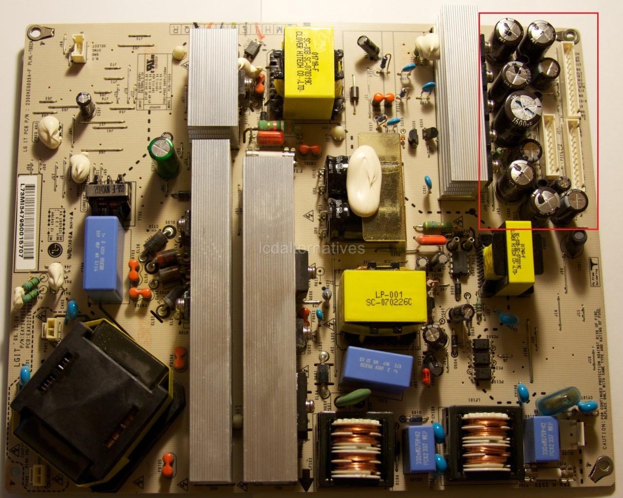
Quick update... the item I'm referring to looks very similar to the two items in the bottom right of this image with the blue squares to their rights.
Yet another update... it may be the "transformer choke"... I'm not sure... I'm just hoping that it may be a valid possibility as to what may have been damaged in my little power zap and may hopefully be something I can replace?

They are just chokes (inductors) and look to be on the supply input side. They will be fine.
If you shorted something out then its 99.999% certain that the damage is going to be failed semiconductors... and with it being a man made fault the failure won't be "logical". You will be looking for collateral damage as well.
Although nothing to do with the man made fault aspect, some of the caps (top right) do actually look as though the vents are lifting... unless its an effect of the photograph.
With the greatest of respect, I suspect this is going to be beyond your abilities. Maybe one to chalk up to experience.
They are just chokes (inductors) and look to be on the supply input side. They will be fine.
If you shorted something out then its 99.999% certain that the damage is going to be failed semiconductors... and with it being a man made fault the failure won't be "logical". You will be looking for collateral damage as well.
Although nothing to do with the man made fault aspect, some of the caps (top right) do actually look as though the vents are lifting... unless its an effect of the photograph.
With the greatest of respect, I suspect this is going to be beyond your abilities. Maybe one to chalk up to experience.
Thanks Mooly... I should have been more clear... these images aren't of my power board... I was just trying to find an image of a similar component (simply because I haven't put a picture of my actual component online anywhere to be able to link it)... Part of me does suspect this will be beyond my ability... but I'm happy to give it a go... at this point I can't really make it worse than it is in that I can't make it work at the moment anyway. I just know it took me a long time to source a 3D passive monitor and figured I've got bits from previous projects lying around (and a good electronics store nearby) so if it's a case of something can be replaced that will/may well fix the issue, I'm happy to give it a go.
Again really appreciate the response though, as someone with very little experience in the deep details of electrical engineering etc any help is always appreciated.
http://www.pinterest.com/pin/create/extension/
Interesting how some components are at odd angles. The blue box capacitor in the lower middle and the four diodes to the left of the big central heatsinks - installed at odd angles.
Can machines insert components like that ? Or is this a manually stuffed board ?
Can machines insert components like that ? Or is this a manually stuffed board ?
Machines can insert parts like that, no problem.
The reason for the odd placement is probably to get away with a single sided board while still meeting clearences required for safety approval.
The single sided board with wire links aparently makes for a lower BOM cost then the same thing double sided would.
Regards, Dan.
The reason for the odd placement is probably to get away with a single sided board while still meeting clearences required for safety approval.
The single sided board with wire links aparently makes for a lower BOM cost then the same thing double sided would.
Regards, Dan.
You would need to come up with a circuit diagram to stand any real chance of fixing this.
You might get lucky and find there is a CP (circuit protector) or a fusible resistor that's gone open circuit but without seeing a circuit its impossible to say. If any of the power semiconductors on the heatsinks have failed short circuit then that's a sign that there could well be other damage. Although the parts won't be unique and unobtainable, they are almost certainly not off the shelf common items either.
You might get lucky and find there is a CP (circuit protector) or a fusible resistor that's gone open circuit but without seeing a circuit its impossible to say. If any of the power semiconductors on the heatsinks have failed short circuit then that's a sign that there could well be other damage. Although the parts won't be unique and unobtainable, they are almost certainly not off the shelf common items either.
Ok I managed to put the image up on a Wordpress site so hopefully I can finally show at least a portion of the power board that no longer works.

That's looks like a standard AC inlet.
AC in, fuse, RF suppression plus a common mode choke, bridge rectifier and reservoir cap.
A shorted diode would be the only likely fault there.
AC in, fuse, RF suppression plus a common mode choke, bridge rectifier and reservoir cap.
A shorted diode would be the only likely fault there.
I assume that means my best bet is really just to keep checking the auction sites and hope to find a new monitor that way? Thanks for all the help Mooly, it is really appreciated! You clearly know your stuff.
Thanks 🙂
Unless you can find a definite problem then I suspect that is the only viable option. When things short out accidently it can have a habit of causing component failures all down the line.
If those components in the picture are OK then you will have full rectified mains across that electrolytic cap. For 120vac that means a DC voltage of 170 volts and for 230 vac mains a DC voltage of 325. If that is present then those parts are all OK.
- Status
- Not open for further replies.
- Home
- General Interest
- Everything Else
- The Moving Image
- DIY Projectors
- identifying and fixing a fried component?