Hi,
I am confused of the polarity of Philips electrolytic capcistor code 043-47689. The CAP is consited with 1 center pin and 3 case pins.
Cosidering 450V high voltage and uninsulated case, I think center pin should be + polarity. But I am confused with 3 + indicators(printing) in the cap case.
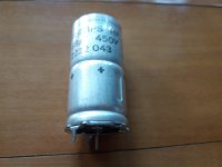
Refer to printings of cap case..
PHILIPS HP
68uF 450V
2222 043
+ + +
advice of identifying polarity of the cap would be appreciated.
I am confused of the polarity of Philips electrolytic capcistor code 043-47689. The CAP is consited with 1 center pin and 3 case pins.
Cosidering 450V high voltage and uninsulated case, I think center pin should be + polarity. But I am confused with 3 + indicators(printing) in the cap case.
Refer to printings of cap case..
PHILIPS HP
68uF 450V
2222 043
+ + +
advice of identifying polarity of the cap would be appreciated.
Attachments
It is just a normal can negative capacitor.
The ribbed can is a sign that it may have quite a good ripple rating.
The ribbed can is a sign that it may have quite a good ripple rating.
Did this come out of something or did you get a bunch of them surplus?
I admit to being confused. The marking seems to imply a positive case, but that would make it a custom part. Apparently it does not match any of the listed PN.
Philips is no longer in the components business so it may be hard to find anyone who actually knows the score.
If you have a large number of them I would hook one up assuming a positive can and measure leakage current at a relatively low voltage. (limit current and be careful!) Hook up another one the other way around, and the one with the lower leakage current hopefully is the correct orientation.
It's confusing me, too!
I wonder if there's an experiment that you could do?
What if you took 20 volts or so, and a 1 kOhm resistor. Set it up to charge the cap in 1 polarity...wait a bit, and measure the voltage...
Repeat the experiment with the other polarity...
Whichever one lets the voltage reach pretty close to the battery voltage is the correct polarity. When the polarity is wrong, the 1 KOhm resistor should limit the current.
If someone knows of a down-side to this, or knows the real answer...of course, please weigh in!
The safest thing to do is test. It may be the case that the offset markings are meant to indicate the center pin is +, but it could equally be that the case is positive.
Philips spun off the components division decades ago. The lighting division got partially spun off at the beginning of the last year.
Philips spun off the components division decades ago. The lighting division got partially spun off at the beginning of the last year.
What if you took 20 volts or so, and a 1 kOhm resistor. Set it up to charge the cap in 1 polarity...wait a bit, and measure the voltage...
Repeat the experiment with the other polarity...
Whichever one lets the voltage reach pretty close to the battery voltage is the correct polarity. When the polarity is wrong, the 1 KOhm resistor should limit the current.
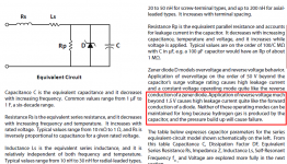
I'd suggest 3.0 volts and 30 Kohms instead. The Aluminum Electrolytic Capacitor application guide from Cornell Dubilier, suggests that reverse voltage beyond ~ 1.5 volts, will cause leakage current to flow (similar to a diode with 1.5 volt Vfwd). See red box in excerpt below.
So, I'd suggest 3V and 30K, giving a current of 50uA which ought to be relatively safe for short periods of time. Whichever orientation gives the higher capacitor voltage, is the correct orientation. Especially so if the incorrect orientation clamps the voltage hard, at ~ 1.5 volts.
_
Attachments
It looks more like they shoved it thru the same printer as the axial ones in the same data sheet.
That makes more sense to me than anything else.
That makes more sense to me than anything else.
Datasheet says:
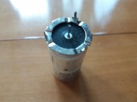
*** BAND *** indicates NEGATIVE terminal and there is a band visible at the far end of the first picture, not shown on the second, so case is negative.
A sideways picture would have been way more clear, wonder why you didn´t post one.
*** + sign *** indicates positive terminal direction, which is at the end where you see an insulated terminal.
IF a + sign printed on a cap body meant "positive case" then all these would be so ... clearly they are not:
An externally hosted image should be here but it was not working when we last tested it.
It is not complicated at all.
ALL, without exception, polarised electrolytic capacitors have the can as negative.
ALL, without exception, polarised electrolytic capacitors have the can as negative.
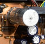
The can is negative, these Philips caps crop up frequently in various forms in consumer equipment.
Here is the 6800uF reservoir cap in the early CD players. Can marked as + (but its the negative). It must be some in house code or marking.
No.
Please read post#12 or to be more precise, look at the pictures.
* Case is marked as negative, notice the black band to the right of text block.
* positive terminal end is shown by "+" sign to left of text block.
It´s not proprietary or obscure polarity marking but the Industry standard.
Of course anything will be printed on cap body/can ... there´s nowhere else to do so.
Thanks. When handling dozens of parts was the day job I suppose the finer points of why they mark something the way they do never crops up. A bit like looking at a resistor, you don't see the colour bands, you just mentally see the value.
(and please do not misquote by changing sections to bold type as that changes the emphasis of the original in a way that the original poster did not intend)
(and please do not misquote by changing sections to bold type as that changes the emphasis of the original in a way that the original poster did not intend)
- Status
- Not open for further replies.
- Home
- Design & Build
- Parts
- Identify polarity of Philips electrolytic capacitor