Hi everyone,
I'm new here, I found this place after looking for an integretad circuit in my sound card through the web... I hope I'm in the right section.
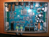
My M-Audio USB soundcard is not working anymore, after a few volt measure and a visual control I think that I found the problem et I'm thinking about fixing it.
Here it is (not my pictures), on the right top there is an IC referred as U22 with 8 pins, a very small one :
https://gearfoxblog.files.wordpress.com/2015/10/img_20150129_0048341.jpg
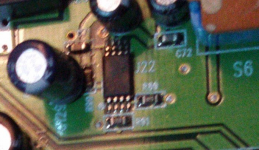
On this second picture it is referred as 57 2110 :
https://gearfoxblog.files.wordpress.com/2015/10/boardchips.jpg
But on mine I read 05 2110.
First of all, does anyone has an idea of what it is and where to buy it ?
Secondly, do you think I can fix it by myself ? I only have a regular soldering iron.
Sorry for my English and thanks a lot for your time and answers.
I'm new here, I found this place after looking for an integretad circuit in my sound card through the web... I hope I'm in the right section.
My M-Audio USB soundcard is not working anymore, after a few volt measure and a visual control I think that I found the problem et I'm thinking about fixing it.
Here it is (not my pictures), on the right top there is an IC referred as U22 with 8 pins, a very small one :
https://gearfoxblog.files.wordpress.com/2015/10/img_20150129_0048341.jpg
On this second picture it is referred as 57 2110 :
https://gearfoxblog.files.wordpress.com/2015/10/boardchips.jpg
But on mine I read 05 2110.
First of all, does anyone has an idea of what it is and where to buy it ?
Secondly, do you think I can fix it by myself ? I only have a regular soldering iron.
Sorry for my English and thanks a lot for your time and answers.
I see, and yours are all the same size.
The problem is that this particular IC is the only one in this sound card !
And it is different from all the others that are the same size as yours, but probably "2115 5026U JRC".
I'm sorry if the IC is hard to find on the pictures, but it is the smaller one on the top, the one the closest to the push button.
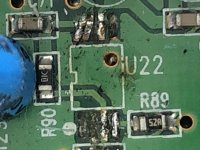
Here's a zoom on the right one, I can't make a good picture because it's kind of brown/burnt on mine and I can't find a better quality on the web.
https://www.diyaudio.com/forums/attachment.php?attachmentid=947070&stc=1&d=1619637708
https://www.diyaudio.com/forums/attachment.php?attachmentid=947070&stc=1&d=1619637708
Attachments
NJM2115 ? Dual operational amplifier.
From the datasheet: The NJM2115 is improved version of the NJM2100.
On the other hand the NJM2110 is a mic amp.
Check to what it is connected to find out which type You have.
From the datasheet: The NJM2115 is improved version of the NJM2100.
On the other hand the NJM2110 is a mic amp.
Check to what it is connected to find out which type You have.
If you don't have a macro lens to take the picture, put a magnifier or reading glasses in front of your camera or smartphone.
Also shine a bright light on it, like a LED flashlight.
Also shine a bright light on it, like a LED flashlight.
The NJM2115 are the ones that look like the NE5532 from gpapag, but not the one I look for.
So it should be the 2110.
Here's the best picture I reached to do...
https://www.diyaudio.com/forums/attachment.php?attachmentid=947212&stc=1&d=1619683932
It is connected to the push button, the 5 Volts from the USB go to the A.
It goes out from the B when the button is on ON position and enter the IC.
The other fact that makes me don't find this component anywhere, is that it measures 5mmx3mm and the pins are on the smaller side (the 3mm one) contrary to the other ICs like the NJM2115 for example that are 5mmx5mm.
Attachments

I may have finally found :
TPS2110 Mux Datasheet pdf - Power Mux. Equivalent, Catalog
What do you think about it ?
TPS2110 Mux Datasheet pdf - Power Mux. Equivalent, Catalog
What do you think about it ?
This is kind of new for me, before I buy the component and try to solder it, I have removed the old one, it has broken with no resistance, maybe because It was burnt...
https://www.diyaudio.com/forums/attachment.php?attachmentid=948077&stc=1&d=1619950352
Is it cleanable ? Will I be able to solder a new one ?
https://www.diyaudio.com/forums/attachment.php?attachmentid=948077&stc=1&d=1619950352
Is it cleanable ? Will I be able to solder a new one ?
Attachments
Urghh... that doesn't look good.
So... for an experienced tech fitting a replacement is still easily doable despite the damage.
You need to use braid to remove all excess solder from what is left of the pads and then clean that area with ISO or meths to remove all traces of burnt flux.
If the tracks remaining will straighten and lie flat then they can be used. For the broken traces you need to carefully solder a single strand of wire from sound print to the IC pin. The wire run fill follow the line of the original print.
It can be done and done neatly so that you would not even detect the damage on a causal inspection but it is hardly the thing to be learning on tbh.
You should also draw a quick diagram showing the connectivity of the print so that you can then confirm it is all correct once a new part has been fitted and that all points that should be in electrical contact in fact are.
This chip has really exterminated your board...
What does it do? If it's just a USB power switch, maybe it's an occasion to bypass that and power your soundcard with a linear PSU. That would probably be easier: locate main supply capacitors and solder wires there.
What does it do? If it's just a USB power switch, maybe it's an occasion to bypass that and power your soundcard with a linear PSU. That would probably be easier: locate main supply capacitors and solder wires there.
I saw a PLC where the repair people had used thin enamel wire, the kind used to wind motors, to substitute tracks.
I have myself used Indian made super glue to stick pads back on PCBs.
Sadly, Loctite does not stand the temperature.
But see how expensive it is, for $20 it may not be worth the pain.
Also, it is quite possible other parts are also damaged, ICs burning is not usual.
So your effort may be wasted.
I have myself used Indian made super glue to stick pads back on PCBs.
Sadly, Loctite does not stand the temperature.
But see how expensive it is, for $20 it may not be worth the pain.
Also, it is quite possible other parts are also damaged, ICs burning is not usual.
So your effort may be wasted.
- Home
- Design & Build
- Parts
- Identify an IC - M-Audio USB sound card