Hi Morgan,
The Lenco is all done and dusted, ended up putting a Decca International arm on it. Sounds really great but the whole thing is now 3st weight.
Tried a few things.
Increased the grid stopper of the input triode to 10K. All grid stoppers are on the pins.
Messed about with the grounding of the input lead - made things worse.
Almost certain at this stage that its the input stage, as you can trace the signal from input to output.
Will try a cathode bypass on the Pentode as a last resort.
I know what you mean about the load been on the low side, but the parafeed arrangement should tend to counter that. My main parafeed amp is wisper quiet, but then again it does use a pentode ccs.
Have a feeling that you are pointing in the right direction with the heaters. I have an unusual heater arrangement. Because I only have a free 18V AC winding to use I have the heaters wired in series with a 6R8 dropper resistor between the valves. I have not generally had many problems with heater induced hum in the past (with the exception of a 5687 preamp), so I tend to default to a simple AC arrangement. However with the high gain which the triode section is running at it probably will tend to be more prone to heater hum. Any pointers as to how I might make this arrangement work satisfactorily.
Anyway i'am off to bed now. I will reread you last two post when I can think about them tomorrow.
Shoog
By the way, the hum looks more like a square wave than a sine wave. It has pulses of RF type hash a 50hz intervals with a bit of sine wave in the background. The final hum output is about 20mV. The power supply has a very clean output with about 20mV of sine wave ripple.
Shoog
Shoog
Hi there,
Having slept on the problem I have come to one definate conclusion. Almost all of the hum is been generated in the driver stage. The reason I say this is because the hum on the grid of the Pentode is almost twice the hum at the output. This suggests that the Pentode is injecting hum in antiphase to the triode with the effect of cancelling some of the triodes hum. Unfortunately even if this was a perfect relationship with full cancellation, I think you would be left with a large component of hash which would be very objectionable.
The real question then is - Is the hum heater induced or simply picked up by the grid of the triode ??
Having listened to it now for a while it sounds great. It obviously distorting the signal a little, but this seems to be in a positive thickning way.
Shoog
Hi there,
At last real progress. I hadn't ground the heater winding. Adding a ground strap has just about eliminated the hum with no source connected. There is a small residual hum which probably will respond to a beefier supply filter.
With a source connected the amp buzzes badly. This I think is a ground loop which hopefully will go if I disconnect the input cable screen at the valve bass, and run an earth strap back from the phonos.
Shoog
Hi again,
Listening to the little beast now.
The problem with hums is that they rarely turn out to be a single issue, and even more rarely are they what you thought they were. The good new is that my hum is gone (I think), no source connected and its quiet. Source connected and all I can here is my rather noisy sound card. Won't know for certain until I try it again on my main system.
Grounding the heater winding was the main thing. Second thing was to put an earth strap between the two halves of the metal case. There was at least a volt of induced noise on the circuit side of the case - which those sensitive grids were undoubtably picking up. Finally I left the input cable screen connected at both end, but tided them together at the the phono sockets.
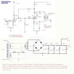
Overall I am very pleased with the sound. Rich and full, but with no hint of valve euphonics. A very cheap way to make a nice headphone amp. If anyone is really interested I will post a revised schematic with power supply details.
Shoog
Listening to the little beast now.
The problem with hums is that they rarely turn out to be a single issue, and even more rarely are they what you thought they were. The good new is that my hum is gone (I think), no source connected and its quiet. Source connected and all I can here is my rather noisy sound card. Won't know for certain until I try it again on my main system.
Grounding the heater winding was the main thing. Second thing was to put an earth strap between the two halves of the metal case. There was at least a volt of induced noise on the circuit side of the case - which those sensitive grids were undoubtably picking up. Finally I left the input cable screen connected at both end, but tided them together at the the phono sockets.
Overall I am very pleased with the sound. Rich and full, but with no hint of valve euphonics. A very cheap way to make a nice headphone amp. If anyone is really interested I will post a revised schematic with power supply details.
Shoog
Shoog said:If anyone is really interested I will post a revised schematic with power supply details.
Very much so...
dave
Hi dave,
I will work something up in the next few days.
I put in a complete screen between the power supply and the main amp. This has reduced the hum even more. Still you like to have a completely hum free headphone amp - but i'am not there yet.
I don't like to have to many huge boxes lying around so I always try to cram them into to small a case.
Shoog
Shoog,
Good to hear about your progress towards hum freedom!
What is the gain like? Don't you have more gain than necessary
in the HP amp? If so, I guess your sound card would seem much
quieter if you got rid of some. Computers make a terrible racket -
putting the amp a good distance from the computer tends to be
a good idea, but I guess you've tried this.
Time to try a 220k (or so) resistor from anode to anode, perhaps?
I'm curious as to what this will do. Did good for me. 😉
(If gain falls too much, there's always the option of paralleled
secondaries on the transformer, to get a smaller step-down. Which
will also increase output swing a bit, since that will probably be
voltage- rather than current-limited.)
Morgan
Hi Morgan,
Gain is a fraction high. Might just try the partial feedback option. Might help to kick that hum into touch, most of whats left is induced hum off the case, and its a bugger to eliminate.
Included the cathode bypass at 1000uf, filled out the sound a little.
Shoog
Gain is a fraction high. Might just try the partial feedback option. Might help to kick that hum into touch, most of whats left is induced hum off the case, and its a bugger to eliminate.
Included the cathode bypass at 1000uf, filled out the sound a little.
Shoog
Hi all,
Put in 180K of Plate to Plate feedback. Reduced the gain a little, killed the remaining hum, and filled out the sound to a very pleasing degree.
Will post the schematic tomorrow.
Shoog
Put in 180K of Plate to Plate feedback. Reduced the gain a little, killed the remaining hum, and filled out the sound to a very pleasing degree.
Will post the schematic tomorrow.
Shoog
Congrats on a successful project - at last! 😀
I'm sure there are many more tweaks that will be tried eventually,
but if you're like me you'll want to listen and let the thing break in
properly for a while.
Something I've always planned to do, but rarely seem to get around
to, is to review the project and analyse each step in the trouble-
shooting process. I think there are things to be learned for the next
project (as well as generally) in such a strategy. Myself, I just don't
keep notes, so I usually forget too soon what I've done to arrive at
a good result.
At least here on the forum, there are the archived posts to serve
one as mnemonics. 😱
Happy listening,
Morgan
Just came across this thread. Nice little project. I'm getting together the stuff to build a low power resistor loaded amp from Steve Benche's site. One question on your design: Why not put the parafeed cap on the ground side of the OPT? You can use a lower rated cap. Maybe at these voltages though the cost would not be much different.
Sheldon
Sheldon
I had to hand some nice 4.7uf caps which are rated at 170V (not quite there but I think it should be OK). I always have slight concerns about the safety of putting the cap in the return leg, just in case there is an interwinding short.
Shoog
Shoog
"Thanx. You should save that as a gif. The noise in the jpg makes it a bit hard to read."
I know, but I did it in "Gimp" by a proccess of cut and paste. Does anyone know of a good schematic drawing program which works in Linux land. Someone mentioned Eagle to me but I think this is windows based.
Shoog
I know, but I did it in "Gimp" by a proccess of cut and paste. Does anyone know of a good schematic drawing program which works in Linux land. Someone mentioned Eagle to me but I think this is windows based.
Shoog
Morgan L wrote:
"Congrats on a successful project - at last!"
Hmm, just realised this could be misinterpreted... Just meant it
took a little while, but then any original design usually does.
(No ref. intended to any of your other projects, that is!) I think
I will actually have to try this design myself!
A couple of minor notes:
Not sure though why your input grid stopper is so big while the
pentode GS is quite small? Might try equalising this a bit by using
1k in both positions. Might not make any difference, though.
Also not sure if current in input stage is sufficient with the plate-
to-plate feedback. Probably marginal, actually. I have a feeling
the sonics would improve with more current. The 180k resistor will
look like something rather a lot smaller to the input stage due to
the feedback action. Though it could be OK with cans, as the
voltage swing required is usually rather small.
Sheldon,
Why would a parafeed cap in the return lead require a smaller
voltage rating? As far as I can see, there is no difference in voltage
requirement whether it's in the "send" or the "return" lead. Either
way, it should be rated same as B+ voltage or a little more to safely
survive start-up. Pre-heating the heaters lowers the requirement,
but I would anyway use a 200-250V part here.
Morgan
Shoog said:Someone mentioned Eagle to me but I think this is windows based.
The one i decided not to use on my Mac was X11 based so i can't see it not running under Linux.
dave
Morgan, I seem to remember from my examination of the datasheet that the Triode doesn't really like to stay linear and deliver more current. I have a strong feeling that the 200K and 2K2 was the only sensible operating point. I would have to check the data sheet to be certain.
Shoog
Shoog
- Status
- Not open for further replies.
- Home
- Amplifiers
- Headphone Systems
- Ideas for using a pair of ECL82 in a headphone amp.