The gain provided by the current mirror is indeed essential, whatever the topology.
As the actual collector will be measured, non-linearities from the reference are relatively unimportant
As the actual collector will be measured, non-linearities from the reference are relatively unimportant
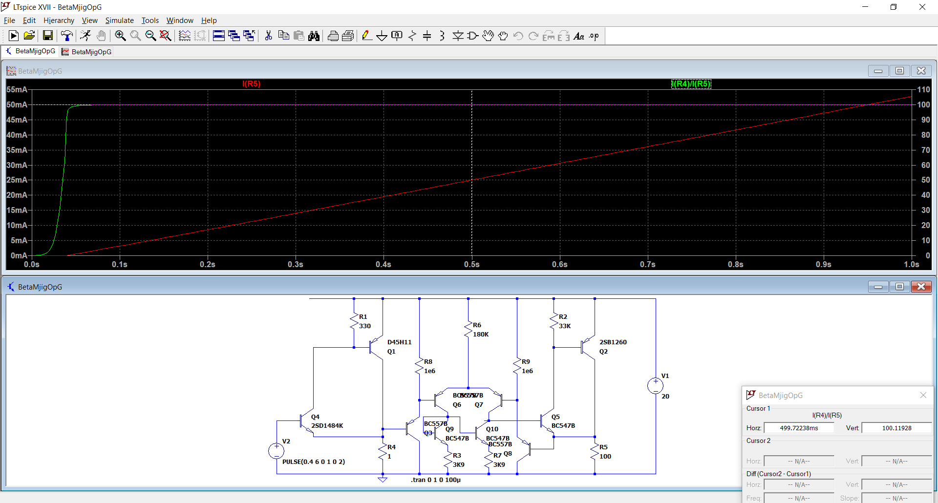
I think this would be improved if you replaced R3 and R7 by a current mirror, and added a trimpot in the emitters of Q6 and Q7; and add the 99 ohms in series with Q3.
It may also benefit from an oscillation suppression cap base-collector of Q8.
The trimpot can be used to maximise the current range linearity.
It may also benefit from an oscillation suppression cap base-collector of Q8.
The trimpot can be used to maximise the current range linearity.
Yes, in the end we always get back to the current mirrors, but they alone are quite sufficient for a 1:100 current range.
The balancing of source impedances is not required, since the input current is in the nA range.
The balancing of source impedances is not required, since the input current is in the nA range.
Now, I have another problem to solve: the Q3 & Q8 of the opposite polarity have their BC junctions forward-biased when the voltage across R4 and R5 nears 1 Vbe.
I have finally found a satisfactory solution: simple and high performance.
The current ratio of 1:100 holds for a 1:1,000 range, ten times better than what I required.
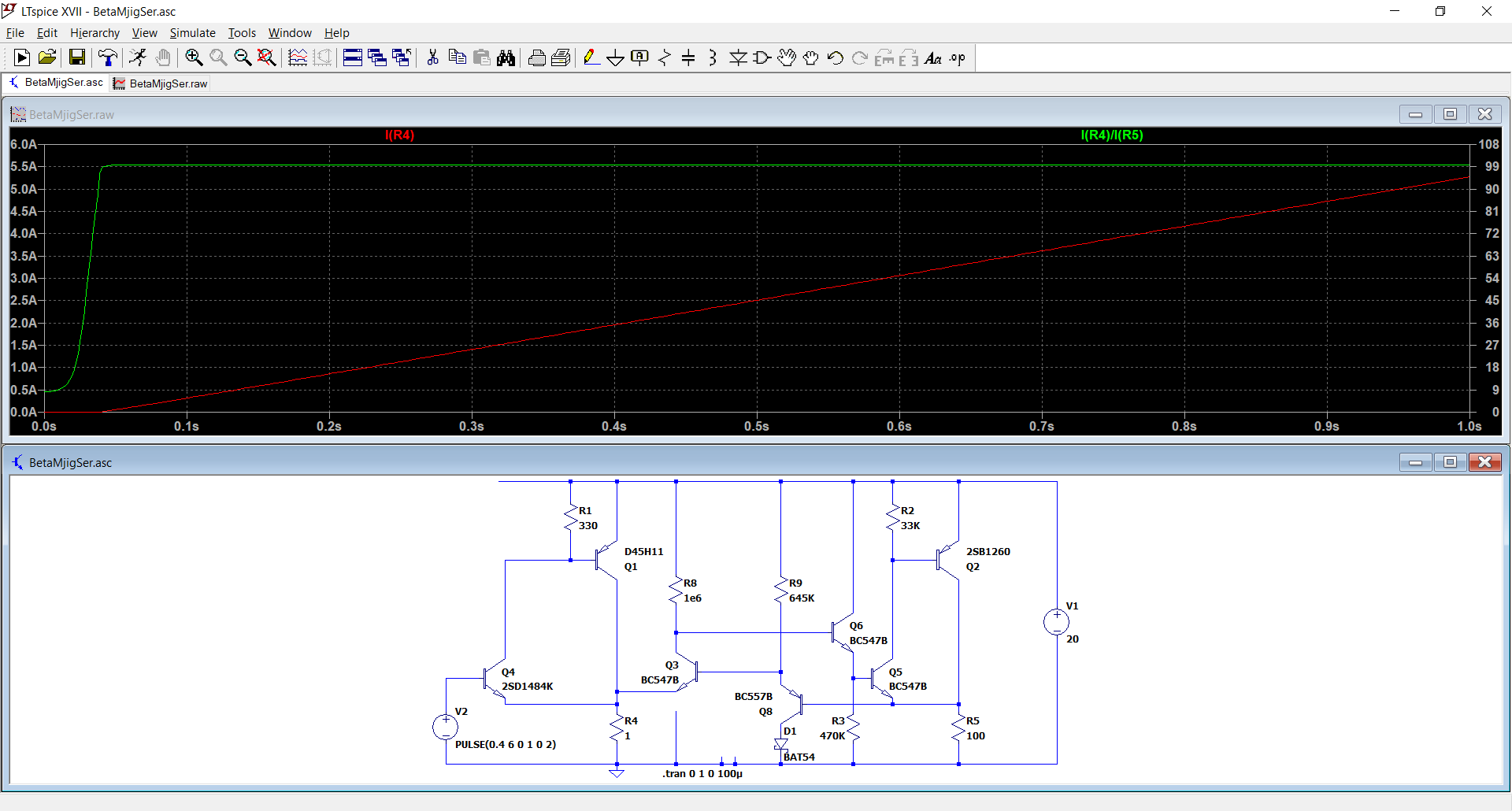
Q3 is the gain stage/error amplifier, and Q8 provides buffering and Vbe compensation.
R9 needs to be tweaked wrt. R8, because the transistors aren't perfect compliments, and a schotkky has to inserted in Q8's collector, to accommodate for the opposite polarity, leaving it only 0.4V Vce to operate at the minimum current, but it seems to work well enough in sim
The current ratio of 1:100 holds for a 1:1,000 range, ten times better than what I required.
Q3 is the gain stage/error amplifier, and Q8 provides buffering and Vbe compensation.
R9 needs to be tweaked wrt. R8, because the transistors aren't perfect compliments, and a schotkky has to inserted in Q8's collector, to accommodate for the opposite polarity, leaving it only 0.4V Vce to operate at the minimum current, but it seems to work well enough in sim