Hi Folks,
here is the start of my idea for a modular preamp.
The pic shows the control (without audio) schematic for a modular preamp with 10 slots for different in/out modules.
happy to answer your questions to this and open for additional ideas.
regards
HP
here is the start of my idea for a modular preamp.
The pic shows the control (without audio) schematic for a modular preamp with 10 slots for different in/out modules.
happy to answer your questions to this and open for additional ideas.
regards
HP
Attachments
With a project as complex as that, a lot of attention has to be paid to:
a] Audio circuits, commons
b] DC supplies, common
c] Control / Logic / Digital circuits, commons
d] attachments to chassis
e] Shield attachments
a] Audio circuits, commons
b] DC supplies, common
c] Control / Logic / Digital circuits, commons
d] attachments to chassis
e] Shield attachments
Hi Speedskater,
yes, you are right......in the pcb layout I took some attention on the commons layout that there are no circles. In general I see separate supply and commons for audio supply (+-18V) and control logic circuits (+24V).
Generally the audio signals from the in/out stages were switched with a relay crossbar with relays from old studio-equipment (Ampenol C2H-24).
The front panel will have an input selector rotary switch with leds for the switch positions, cause the inputs can change depending of the different boards in the 10 slots. The green leds show that there is a board in the slot no. x and this dual red/green led shows channel overload with red. The same for the output rotary switch.
at this time I want to use as input boards:
lets see what happens when I have all this together.
thanks for your interest....
HP
yes, you are right......in the pcb layout I took some attention on the commons layout that there are no circles. In general I see separate supply and commons for audio supply (+-18V) and control logic circuits (+24V).
Generally the audio signals from the in/out stages were switched with a relay crossbar with relays from old studio-equipment (Ampenol C2H-24).
The front panel will have an input selector rotary switch with leds for the switch positions, cause the inputs can change depending of the different boards in the 10 slots. The green leds show that there is a board in the slot no. x and this dual red/green led shows channel overload with red. The same for the output rotary switch.
at this time I want to use as input boards:
- line in unsym (RCA)
- phono MC
- phono MM
- line in sym with transformers (XLR)
- streaming board with Wifi and network
- line out unsym (RCA)
- line out sym with transformers (XLR)
- small speaker amp with 2 x 15W
- output by streaming to network
lets see what happens when I have all this together.
thanks for your interest....
HP
I would consider Rod Elliots simple mic amplifier. I have simulated it and It has spectacular performance especially considering it uses only two bipolar transistors. It leverages constant current and bootstrap technique to provide high gain. The gain can be controlled with one pot/resistor.
Add a buffer to the output and it will drive 600ohm line with very little distortion/noise.
https://www.sound-au.com/project13.htm
Add a buffer to the output and it will drive 600ohm line with very little distortion/noise.
https://www.sound-au.com/project13.htm
Hi All,
the project is on a good way.
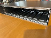
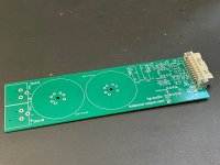
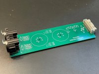
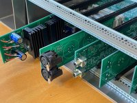
now some work with the enclosure (the 1st pic show the backside with the pcb slots)
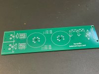
and the other pic the connection bus pcb from both sides.
regards
HP
the project is on a good way.
now some work with the enclosure (the 1st pic show the backside with the pcb slots)
and the other pic the connection bus pcb from both sides.
regards
HP
Attachments


Hi folks,
yesterday the pcbs arrived.......
HP
yesterday the pcbs arrived.......
HP
Attachments
-
 IMG_0769.JPEG556.6 KB · Views: 60
 -
 IMG_0768.JPEG626.7 KB · Views: 63
 -
 IMG_0767.JPEG534.7 KB · Views: 56
 -
 IMG_0766.JPEG543.6 KB · Views: 57
 -
 IMG_0765.JPEG589.6 KB · Views: 63
 -
 IMG_0764.JPEG590.1 KB · Views: 63
 -
 IMG_0763.JPEG545.3 KB · Views: 54
 -
 IMG_0762.JPEG659.9 KB · Views: 55
 -
 IMG_0770.JPEG576.7 KB · Views: 66
Your project seems to be expanding without limits.
The tricky part of having input & output connectors on cards is dealing with cable shields and audio circuit commons.
The tricky part of having input & output connectors on cards is dealing with cable shields and audio circuit commons.

Hi Speedskater,
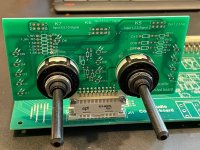
this is right....but all cards are input cards OR output cards......never both functions on one card.
This preamp also uses separate relais crossbars for input and output signals. You can see this on pic 0762.
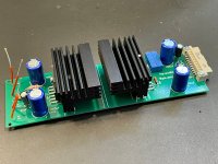
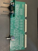
The small card with the heatsinks (pic 0769) is a small power amp card with 2 x 18W........made it just for fun and cause it also fits in the rack as a prelisten amp.
Lets see what ideas for additional cards come up.......
Depending on the cards I put in, there can be 10 different input cards, or 9 input cards and one output card, or 7 input cards and the maximum of 3 different output cards.
The Power amp project is also kicked off.
HP
this is right....but all cards are input cards OR output cards......never both functions on one card.
This preamp also uses separate relais crossbars for input and output signals. You can see this on pic 0762.
The small card with the heatsinks (pic 0769) is a small power amp card with 2 x 18W........made it just for fun and cause it also fits in the rack as a prelisten amp.
Lets see what ideas for additional cards come up.......
Depending on the cards I put in, there can be 10 different input cards, or 9 input cards and one output card, or 7 input cards and the maximum of 3 different output cards.
The Power amp project is also kicked off.
HP
- Home
- Design & Build
- Electronic Design
- ideas for a modular preamp