Lately I got a bug to build a fleapower amp using the early globe style 5 pin tubes. I picked up a pair of RCA 47 and a pair of 27 tubes and have a pair of 8W 7K OT. Probably going to get a matching globe type 80 rectifier to go with it. Not seeing much online as far as schematics, but it shouldn't be too hard to come up with something. I think this will be a fun project!
Anyone have some ideas or seen schematics for using these early tubes?
Anyone have some ideas or seen schematics for using these early tubes?
Would a variant of your 6SQ7 amp work? I have a couple of 1930's radios that use that driver (2A6 in one of them) but into 2A3.
I'm hoping to do something similar with 1619, considering a loftin-white schematic as an option.
I'm hoping to do something similar with 1619, considering a loftin-white schematic as an option.
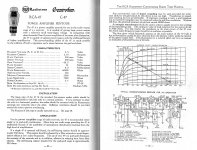
I have started last year a small power amplifier build, entirely equipped with mid-'30 globe tubes. They are always slightly microphonic and tolerances are worse than later tubes, so my goal is mostly the recreation of a century old design with modern transformers and components that may hopefully be good enough for Hi-Fi use. 47 - 27 - 80 has also been my tube choice because they are still easily available as globe at reasonable price. Starting pointof my design is the RCA/Cunningham application note for the 47 tube. It gives a pretty detailed specifiation of the output stage. The 27 preamp stage was usually coupled to the power stage with a 1:3 step-up transformer. A quality Hi-Fi part will be expensive, so I will first try a inexpensive OEP z218a2e (rs components part number 667-6076) that I've already tested as input transformer on another project. It is not meant to be used as interstage transformer, so I am still searching for a better suited and easily available part in the 10-15 EUR price range. If a suitable interstage transformer could not be used, then I will use RC coupling, but maybe a single 27 tube will not be enough to give the required voltage swing at the grid of the 47 tube. My goal on power supply design is to have it as simple as possible. 250V B+ supply will be LCRC for the output stage, with an additional RC for the 27 tubes. The PSUD2 free simulation software is pretty accurate. As filament supply for the 27 and 47 tubes I will first try AC power: 4 separate windings made with a few enameled wire turns around a standard toroidal transformer. If the hum wil be excessive, I am thinking about low-cost insulated DC-DC converters, big enough to supply the turn-on surge at 10x the steady state value. 3.3V is a standard value and can be brought down to 2.5v with a RC filter cell. But if the filament power for preamp tubes must be DC, then I will probably try a directly heated tube. This way the turn-on time of the amplifier would be 2-3 seconds, comparable with a modern amplifier or even quicker (most devices today need to wait for the embedded microcontroller to boot). This will be another conversation point.
My project is now temporarily halted while I am thinking about a suitable chassis for this amplifier. It would be nice to have something in the style of the '30. On my collection I have two PA amplifiers of that era and they are very cute. The color scheme is also surprising. Original paint on one of them is hammered light blue, it would have been considered frivolous for a professional device on the following decade, and maybe even today. I've heard that the 1930 were a colorful time, and it may be true.
My project is now temporarily halted while I am thinking about a suitable chassis for this amplifier. It would be nice to have something in the style of the '30. On my collection I have two PA amplifiers of that era and they are very cute. The color scheme is also surprising. Original paint on one of them is hammered light blue, it would have been considered frivolous for a professional device on the following decade, and maybe even today. I've heard that the 1930 were a colorful time, and it may be true.
Attachments
Last edited:
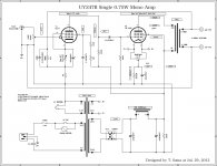
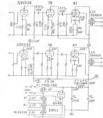
These are the schematics for SE amplifiers with the 47 (= UY274B) in pentode mode that I have in my collection. I didn't check them thoroughly though.
The third one has three stages but no GNFB, so probably the input sensitivity is (unpractical) high.
The third one has three stages but no GNFB, so probably the input sensitivity is (unpractical) high.
Attachments
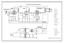
These are the schematics for SE amplifiers with the 47 (= UY274B) in pentode mode that I have in my collection.
That second amp might be able to be used without the triode strapped 57 as a starting point for ideas, thanks!
Would a variant of your 6SQ7 amp work? I have a couple of 1930's radios that use that driver (2A6 in one of them) but into 2A3.
I'm hoping to do something similar with 1619, considering a loftin-white schematic as an option.
I was hoping to use 5 pin globe style tubes, I do have some metal 6SQ7 from that era I could use. Is there a 5 pin equal to the mu of a 6SQ7?
Last edited:
I'm building this amp more for aesthetics than performance so would really like to stick with the old globe type tubes. The 2A6 does look like something interesting to use to drive a KT88 type amp in the future 🙂
I got some responses in another forum about using a 3:1 interstage transformer or possibly a choke load on the 27 to get the voltage swing up. Does that seem like an option? I really do not want to use ST or coke bottle shaped tubes and using these globe style is more important to me that the fidelity.
Someone suggested I take a look at the 56 for a globe triode with more drive. It's got about 50% higher MU than the 27 so might be a good route to take.
- Home
- Amplifiers
- Tubes / Valves
- Ideas for a 47 SE amp in pentode mode.