Hi all,
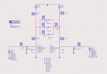
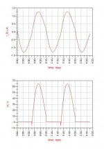
I am designing this CMCD-PA using Agilent ADS. I would like to know, why did the voltage at output load (R4) form a half sinusoidal shape?
Shouldn't it be a full sinusoidal waveform, similar to the current at R4??😕
You can refer to my schematic and the output in the attachment below.
TQ
I am designing this CMCD-PA using Agilent ADS. I would like to know, why did the voltage at output load (R4) form a half sinusoidal shape?
Shouldn't it be a full sinusoidal waveform, similar to the current at R4??😕
You can refer to my schematic and the output in the attachment below.
TQ