The documentation I saw at the time this started to take off showed less harmonics, because the the charging opening angle is wider. I think there's a sim test circuit available.
Edit:Of course, see attached.
Jan
Edit:Of course, see attached.
Jan
Attachments
Last edited:
Have you considered using GaN transistors?
The "switching" frequency of this synchronous rectification circuit and the modest voltage requirements herein basically wastes any advantage SiC/GaN transistors provide. This is definitely a place to look for slower plain-Jane Si very-low R_dson/modest C_gs switching transistors sized appropriately for the load requirements.
When you want a high efficiency >1 MHz switching power supply network, then the exotics make a lot more sense.
...
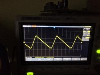
One thing I am unsure of, is how the transients of the resulting sawtooth wave looks after the bulk cap? Does it even look like a diode sawtooth? Or will it be a total mess? ...
At full load on my Zeno regulator. Measured directly on the cap after Saligny.
Regards,
Tibi
Attachments
GB list is open till 1st March.
Saligny - Ideal bridge - open till 1st March - Google Sheets
Regards,
Tibi
Saligny - Ideal bridge - open till 1st March - Google Sheets
Regards,
Tibi
If anyone saw the circuit of the factory amplifier please tell him his model in which they use the controller of an ideal diode bridge on field-effect transistors instead of ordinary diodes. Type LT4320 and analogues.
That's a YouTube "Alternative Health Audio website" - an alternative travel to internal meditation?
Your chance to get the best rectifier will end in two days.
There will not be a second group buy.
Regards,
Tibi
There will not be a second group buy.
Regards,
Tibi
Hi Tibi,
I'd like to use this on a CCRC PSU for a Class A amplifier, which will be using 3x 68000uF, 8 mOhms ESR caps per rail and the R will be 0.1 Ohm. I was planning to use two bridges for the PSU (one per rail). Do you think the inrush would be too high for these bridges?
Thanks
Do
I'd like to use this on a CCRC PSU for a Class A amplifier, which will be using 3x 68000uF, 8 mOhms ESR caps per rail and the R will be 0.1 Ohm. I was planning to use two bridges for the PSU (one per rail). Do you think the inrush would be too high for these bridges?
Thanks
Do
Last edited:
Hi Do,
You might want to look at the ESR of the CRC caps. In this application, low ESR is not always good as it has very high ripple current and high turn on transient. For Class A power supply the current is steady so need for ultra low ESR is not justified like Class AB amps. Check ripple current rating of those caps and good rule of thumb is that ripple current is about twice steady state current.
These active bridges are very attractive for Class A where running a 5A bias current will result in many watts of dissipation vs <1w with the active bridge.
Hi Tibi,
I'd like to use this on a CCRC PSU for a Class A amplifier, which will be using 3x 68000uF, 8 mOhms ESR caps per rail and the R will be 0.1 Ohm. I was planning to use two bridges for the PSU (one per rail). Do you think the inrush would be too high for these bridges?
Thanks
Do
Saligny will handle very high peak currents, far above your transformer capability. What you need to take in consideration is your trafo secondary that, for sure, will need to deliver serious current to keep these caps charged and as xrk971 mentioned, low ESR is not the right choice in class A operation.
Regards,
Tibi
- Home
- Group Buys
- Ideal bridge rectifier GB