Hi all,
I've built some conventional speakers in the past, but I'm just now getting into the ESL thing. I have done some reading on the internet and I'm attracted by the superior sound quality this system should provide. As far as I understand, there are only two disadvantages to an ESL:
1: The response of the lower frequencies, say below 100Hz, which can be easily solved by using a hybrid system with a 'normal' dynamic woofer.
2: An ESL is extremely directional, which can be dealt with by making several sections, but making these sections hase several disadvantages for the sound quality.
Also, a tall ESL (of say 20 to 30cm wide and 120cm high) is said to have better dispersion and better placement than a wide ESL.
Now here comes the idea that popped into my mind this evening:
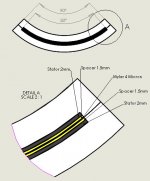
Why not make a tall, partial round ESL to enhance dispersion and optimize sound quality?
I have attached an image to clearify the idea.
Of course somebody else already thought of this, but I cannot find any info on this forum or the internet.
Of course it's a little harder to build than a flat ESL, but no too hard I think.
Also the Mylar film would be in a bent position which would stiffen it, but because it's only 4 micron thick I expect this to be unsignificant for it's movement (and thus the sound quality).
Maybe somebody here could come up with some more pro's and con's for this idea!
Kind regards,
Emiel
I've built some conventional speakers in the past, but I'm just now getting into the ESL thing. I have done some reading on the internet and I'm attracted by the superior sound quality this system should provide. As far as I understand, there are only two disadvantages to an ESL:
1: The response of the lower frequencies, say below 100Hz, which can be easily solved by using a hybrid system with a 'normal' dynamic woofer.
2: An ESL is extremely directional, which can be dealt with by making several sections, but making these sections hase several disadvantages for the sound quality.
Also, a tall ESL (of say 20 to 30cm wide and 120cm high) is said to have better dispersion and better placement than a wide ESL.
Now here comes the idea that popped into my mind this evening:
Why not make a tall, partial round ESL to enhance dispersion and optimize sound quality?
I have attached an image to clearify the idea.
Of course somebody else already thought of this, but I cannot find any info on this forum or the internet.
Of course it's a little harder to build than a flat ESL, but no too hard I think.
Also the Mylar film would be in a bent position which would stiffen it, but because it's only 4 micron thick I expect this to be unsignificant for it's movement (and thus the sound quality).
Maybe somebody here could come up with some more pro's and con's for this idea!
Kind regards,
Emiel
Attachments
Martin-Logan curves ESLs. It really doesn't do much for high freq dispersion because the driver is still very wide relative to the HF wavelengths. They curve them to make the stators stiff, not the diaphragm.
If you make the driver tall and narrow, there's no need to curve it. It will have relatively wide HF dispersion without a curve, and adding a curve only makes construction about 10x harder. When you put a diaphragm under tension and try to bend it around a curve, it will form a saddle and come into contact with the rear stator. You have to put most tension in the vertical axis, and just a little in the horizontal axis to pull out wrinkles. This is why ML uses so many horizontal spacers to support the diaphragm in their speakers.
The problem with narrow drivers is that while they disperse highs around the room, they can't put out much low freq stuff. Also, maximum SPL is a function of the driver area. Small drivers are not going to give you much, which is why most are made large.
Do you think it is best to spray high freqs all over the room? Some people prefer the directional characteristics of large, flat drivers because it makes room reflection paths predictable and controllable. Much of the localization that the brain does works in the mid to high frequency range. When you spray those freqs all over the room you get multipath that reduces the apparent localization of the sound sources. Nothing "images" like a pair of flat panel ESLs set up for near field listening.
So it depends on what you want. If you want to try tall and narrow, go for it. Try making flat ones before curved units. There's enough to learn about making ESLs without extra mechanical complications.
I_F
Thanks for your reply.
I agree on the fact that a very big angle of dispersion is not desireable. But I would like a dispersion angle of about 35 to 45 degrees to create a somewhat larger 'sweet spot'.
Is there some rule of thumb between the panel width of a flat ESL and the dispersion angle?
Also, referring to the horizontal spacers needed in a curved ESL, would those spacers influence the sound quality in a negative way? You'd divide the total area panel in smaller pieces, would this influence the SPL or frequency range?
Referring to the anticipated construction problems: I have acces to a CNC mill, and I can get perforated sheets of aluminium, steel or stainless steel in any size and pre-bent in any radius at a fairly good price. Also, I'm reasonable experienced in making 3D drawings and constructing prototypes of all kinds of products (this used to be my job). For this reason I don't worry too much about the problems that would occur during the construction.
I'm just curious if there would be real advantages to a curved ESL.
Kind regards, Emiel
Hi,
Ofcourse Martin Logan speakers are not bend to increase rigidity; there are much easier methods to achieve this.
Disperion of flat esls can be calculated with the simple formulas of Huygen/Fresnel but take care for the correct interpretation. The diffraction intensity pattern is largely dependent of the angle most of the time! So a calculated 30 degrees dispersion doesn't mean you will get a smooth response over 30 degrees!
Curved esls are much more difficult to make but it is worth the trouble.
to bend or not to bend....
Hi,
I actually don´t know the true reason why ML bends their panels.
My experience showed that both claimed reasons do work. The dispersion characteristic is widened against a flat panel, but not very much (I understand the claimed 30° as+-15°) and the panel is much stiffer than a flat panel (the mylar-diaphragm is not stiffened as You thougt correctly Emiel). Still You have a very distinct sweet spot. But imo its better for all-the-day-by-the-way-listening.
Of course there are several methods to stiffen a flat panel, but You rarely find one that is so optical pleasing, easy to build and therefore cheap! Has no one realized that by construction the MLs are not superduperhighend but cost-optimized products using off-the-shelf-parts and simple cheap manufacturing? (don´t get me wrong ere: it´s no disregard, but respect for cleverness)
Building a curved panel is not that difficult. The main difference is to build a curved tensioning gauge. You just have to know that You have to tension the diaphragm only parallel to the straight dimension and not -or at least as little as possible- in the curved dimension. Then the diaphragm keeps a cylindrical shape. The major drawback of curved panels is, that for installing the membrane into the tensioning gauge and later onto the stator You´ll most probabely need a helping hand, whereas you can build a flat panel alone! 😉
The horizontal spacers within MLs design (as well as in all other good designs) serve two purposes. The first is to really assure that the diaphragm stays in a cylindrical manner. The second, general and much more important reason is dynamic stability. You´ll find in the literature that a diaphragm should be supported in a way that the shortest free vibrating distances are 70.....100 times the diaphragm-stator-distance (d/s), e.g for a d/s-spacing of 1mm the diaphragm should be supported every 70...100mm. Using greater distances may lead to the membrane touching the stator whilst playing high levels of music, whereas smaller distances reduce efficiency. Especially with hybrid designs the membrane tends to be blown into the stators by the woofer´s pressure waves. ML uses varying distances in their panels (but all within this 1/70...1/100 range), which leads to a broadened and less strong resonance (Fs) A point Roger Sanders negates in his book, but my experience is that it actually is so)
Bent panels are restricted in their ability of linear diaphragm travel. But as long as the d/s can be kept small (and this is the case for all frequencies well above 100Hz) distortion isn´t higher as in flat panels. As a very positive sideeffect the efficiency is high. Every tenth millimeter more in d/s-spacing costs efficiency, so use a as small as possible d/s.
A nice trick to ´overcome´ the differences in membrane behaviour between positive and negative excursions (front-back) is to make the back d/s-spacing app. 10% greater than the front d/s.
There are some major/minor flaws in Your construction pic.
Keep the angle of curvature low. You´ll get enormous difficulties with angles above 40°. 20° to 30° is enough.
Use thin metal sheets. When punched or routed each hole in the sheet does not only look like a BR-canal but it behaves the same way -a bandpass filter! Thick sheets tend to restrict the possible bandwith of the speaker to frequencies within the audio range.
One solution would be to increase the hole diameter, but that leads to a less homogenous and lower field strength. The second solution is to use thinner sheets. When possible with regard to stiffness the second option should be drawn! Here comes the curvature into the game again 😀 Here 1.5mm steel for panels over 2.000cm², 1mm for panels over 1.000cm² and 0.5...1mm for smaller ones is thick enough.
A d/s-spacing of 1.5mm is more than enough. I´d opt for even lower d/s of 1.1mm(back) and 1mm (front) for panels up to 400mm width.
You use such panels from 150Hz on (earliest!! but better is 200Hz...250Hz).
Use very high diaphragm tension (the material should be elongated roughly 1.5% to 2%). With 4µm PET You can reach up to 180Hz (d/s: 1mm, horizontal spacers 70mm apart). This high tension gives You high efficiency and very high dynamic stability. You don´t need high transformer ratios and polarising voltages which leads to a safer panel and less aging stress (corona effects always lead to quicker aging especially of the diaphragm coating, as well as the insulation materials).
ML uses 12µm foil that can withstand higher tensions, so that even 250Hz is possible. They use such high tension because they use the resonance for frequency response purposes. Electrically the panel is crossed over well above the resonance (app. 400Hz, 12dB), but acoustically the crossover point is at 250Hz very steep (>>24dB). This works really good in terms of efficiency (95dB and more is possible), crossover elements count (just a dampened high-Q-12dB-HP, consisting of 3 elements) and measurement, but imo the acoustic footprint of the resonance is audible.
When planning a crossover-freq of lets say 250Hz, use a Fs one octave below and adjust the diaphragm tension accordingly. You have to get rid of the resonance in the freq-response with an additional Notch-filter (higher number of elements) and You loose efficiency, but imo it sounds better.
That´s it for a beginning 😎
jauu
Calvin
Attachments
I'll probably built a curved ESL in the near future, but I'm starting with getting all the electronics right and testing it on a relatively small flat ESL with wire stators. This way I'll be a little more experienced when building the curved ones, and it will not cost me a lot extra.
Currently I'm thinking of an easy-to-build wired stator which also will incorporate a system to bring the diaphragm up to the right tension, so there will be no need to pre-tension the Mylar. I think I've got it all figured out, there's only one thing need to know:
How far, in percentage, should the Mylar be stretched to get it up to the right tension? In other words: if I have a piece of Mylar of say, 1 meter by 0.10 meter in unstretched condition, how large would it be when it's brought up to the right tension?
Of course I'll post my drawings of this idea here when they're ready!
Kind regards,
Emiel
Re: to bend or not to bend....
Sorry, my previous post crossed with yours, my question is answered!!!
Thank you for your posts filled with valuable information, Calvin (and other of course)!
I'm still new to the ESL thing, so sometimes all termes and calculations are dazzling me
I have some specs I would ultimately like to reach, maybe you could help me translate them to the right parameters of the ESL:
Frequence range: 135Hz - 20000Hz +/- 3dB, below they will be actively crossed with 24dB/oct.
Sensitivity: >=89dB/1w/1m, the ESLs will be driven by a 2x30Watt Solid State Class A amplifier.
Max SPL: at least 102dB/1m (I sometimes like to listen to loud music)
Dispersion: > 35 degrees
Thats about it.
I was thinking of an area of about 0.2m2 (1m x 0.2m), a spacing of 2mm, 5000V and a step up ratio of 1:75. Would that do the trick?
Kind regards,
Emiel
Calvin said:
Use very high diaphragm tension (the material should be elongated roughly 1.5% to 2%).
Sorry, my previous post crossed with yours, my question is answered!!!
Thank you for your posts filled with valuable information, Calvin (and other of course)!
I'm still new to the ESL thing, so sometimes all termes and calculations are dazzling me
I have some specs I would ultimately like to reach, maybe you could help me translate them to the right parameters of the ESL:
Frequence range: 135Hz - 20000Hz +/- 3dB, below they will be actively crossed with 24dB/oct.
Sensitivity: >=89dB/1w/1m, the ESLs will be driven by a 2x30Watt Solid State Class A amplifier.
Max SPL: at least 102dB/1m (I sometimes like to listen to loud music)
Dispersion: > 35 degrees
Thats about it.
I was thinking of an area of about 0.2m2 (1m x 0.2m), a spacing of 2mm, 5000V and a step up ratio of 1:75. Would that do the trick?
Kind regards,
Emiel

Hi,
famous last words!!
"...easy-to-build wired stator"
"...I think I've got it all figured out, there's only one thing need to know:" 🙂 😀 😉 🙂 😎
Just kiddin......don´t be upset. 🙂
Follow the link http://www.diyaudio.com/forums/showthread.php?s=&threadid=64620
and have a closer look to the frequency response of the raw panel (Multidioc 1. Panel is 125x25cm). You´ll see that above the strong resonance at 180Hz (Fs) the response curve shows a clear dip (250-700Hz). This is due to acoustic phase cancellation and can only be countered electronically (filter) and/or mechanically (much greater width of the speaker by using wider panels or an open baffle)
This is a typical response curve for an open planar speaker and shows the problem of very low crossover points.
Your specs will be hard to achieve. I actually believe You can´t reach them with Your concept at all without throwing a helllot of work into the panels!
Solutions for this panel size:
- higher crossover freq of min. 250Hz
- reduce d/s from 2 to 1.5mm (with >250Hz 1.0mm)
- take a higher transformer ratio 1:100 or more
- use thin wire (best should be Kynar-isolated wire-wrap-wire of AWG24, AWG26 or AWG30)
- even better, though very hard to get in small quantities is corona resistant magnet wire (not the standard types!!) that are intended for inverter use etc. (wires leave You with the not so trivial prob to get between 300 and 800 of them straight and I mean really really very very straight
 )
)Solution II same crossover:
- bigger panel with min 400mm width
- 2mm d/s
- higher transformer ratio
- use even more thin wires (600 to 1.600) or
- spare the work and use metal sheets 😉
- use massive electrical equalizing
Solution tip:
- work with metal sheets on Your first project (there are enough probs left that can ruin Your nerves)
- restrict freq-range to >200Hz
- keep things simple and work procedures easy
- listen to those humorless grey-haired old men even if their advices sound a little screwed (guess where they lost humor and gained grey hair? 😀 )
jauu
CAlvin
Re:

So you're actually saying the ESL specs I proposed are not feasible without electronic equalizing? What would be the best panel width to reach the 135Hz at -3dB as much as possible, without the EQ and still have good dispersion? (I'd like to reach this frequency because I already have a very nice active LR filter tuned at this frequency and it keeps all the mids coming from the ESL and not from the woofer)
Is making let's say 4 panels of 0.5x0.1m and placing them in a 2by2 matrix at angle of 10 degrees a good idea?
I was planning on using 0.14mm2 wires with PVC isolation (total diameter 1.1mm) at a distance of 2.5mm hart-to-hart, based on the book of E. Fikier.
Still full of questions, and there will be always new ones coming up, man I'm glad this forum exists!😎
Thanks for all the help!
Ciao, Emiel
I'm not that easily upset! 😉 I'm just always full of ideas when starting something new, but usually 99% will seem not feasible later on! (After a lot of brainstorming, browsing this forum and making drawings)Calvin said:Hi,
famous last words!!
"...easy-to-build wired stator"
"...I think I've got it all figured out, there's only one thing need to know:" 🙂 😀 😉 🙂 😎
Just kiddin......don´t be upset. 🙂
So you're actually saying the ESL specs I proposed are not feasible without electronic equalizing? What would be the best panel width to reach the 135Hz at -3dB as much as possible, without the EQ and still have good dispersion? (I'd like to reach this frequency because I already have a very nice active LR filter tuned at this frequency and it keeps all the mids coming from the ESL and not from the woofer)
Is making let's say 4 panels of 0.5x0.1m and placing them in a 2by2 matrix at angle of 10 degrees a good idea?
I was planning on using 0.14mm2 wires with PVC isolation (total diameter 1.1mm) at a distance of 2.5mm hart-to-hart, based on the book of E. Fikier.
Still full of questions, and there will be always new ones coming up, man I'm glad this forum exists!😎
Thanks for all the help!
Ciao, Emiel
Calvin help with some ?? please, as I am new to this.
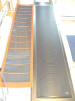
I plan on using egg crate and wire for stators overall size 6" X 48" with a panel size of 5" X 47". For a first panel is there anything wrong with using a larger wire size, say AWG14, and run 10 per inch, I could always make another later down the road. Also with the panel only 5" wide is it necessary to have horizontal spacers, and If I have a d/s of .040 or so how many would I need. And one more? please, Is this attachment correct, if not please help.
I plan on using egg crate and wire for stators overall size 6" X 48" with a panel size of 5" X 47". For a first panel is there anything wrong with using a larger wire size, say AWG14, and run 10 per inch, I could always make another later down the road. Also with the panel only 5" wide is it necessary to have horizontal spacers, and If I have a d/s of .040 or so how many would I need. And one more? please, Is this attachment correct, if not please help.
Attachments
Oh ohhhh...
Hi,
@Emiel
oh my gosh...and I was thinking I were crazy designing a hybrid with a panel of 70x200cm and a dipolar bass tower with 12 drivers per side 😉
But doing this in wire!!! Well....if You´ve really done that successfully, I promise I´ll only call You Mr. Ironman ESL from that day on 😀 😀
To give You an idea of a successfull(?) implementation of that:
have a look at MLs archives for the original old Statement. They claim it to be crossed over at 120Hz and I´m not sure if they used a filter-Q more or less than 1 (probabely >1).
"..(total diameter 1.1mm) at a distance of 2.5mm hart-to-hart" Does this mean +-0,7mm maximum excursion of the diaphragm or +-1,25mm or +-2,5mm??
If You´d use a frame made of 3mm thick spacers, stiffened by lets say horizontal aluminium bars to which the wire would be glued in a vertical manner, You´d end up with 1,9mm excursion. (Think of the Audiostatics! and have a look at the pic).
Using 2.5mm thick spacers and a double sided sticky tape (TESA for carpets, ~0,1mm) You end up at ~1.5mm. This is the easiest way to build and gives a higher efficiency and should just be sufficient for the needed excursion levels.
You could have a stiffening bar every 150mm in height, so You can place diaphragm dampers in form of a small foam strip or a silicon dot right under those bars. But You might need more stiffening for such thin wires, so double the number of bars count (but not the damper count!) In this case You won´t even need to tension the diaphragm mechanically. You can tension it thermally which has some advantages, eg. less material stress, consistancy in parameters and ease of production and will give You a resonance of app. 60-80Hz.
I´d place one wire per 2mm, i.e 1,1mm wire and 0,9mm spacing. That gives You an covered/open-relationship of 55/45 (acoustically, electrically it´s just 25/75). The prob with this wires is, that the electrical coverage-ratio and therefore efficiency is quite bad, because of the thick PVC insulation. This is countered a bit by the dielectric constant of the insulator (which should be high for efficiency reasons, but unfortunately isn´t with most plastics. Luckily PVC as well as polyamides like Kynar range quite high amongst plastics)
Kynar-isolated wire-wrap-wires have thinner insulations which allows for more wires in a more dense fashion (better ratio) and closer proximity of the copper to the diaphragm (remember EVERY 1/10mm counts). Even better are the magnet-wires, because they have the thinnest insulation. Additionally You can get rectangular magnet-wire which allows for even higher field density/strength.
My own old panels were 24x140cm with 30mm spacer-width, 4mm thick. I ended up with app 18x120cm free membrane area. I used H07-VU wire which is PVC-coated with an dia. of 2.8mm. This leaves 2.3mm of excursion after glueing with tape. Thermal tensioning of the membrane gave a Fs of app. 60Hz. Efficiency with a 1:100 trannie was at 80dB/2.83V/1m. Dynamics were still impressive because the maximum SPL was way above 100dB (but the fuses of my Rotel which is capabel of some 300W blew quite often )
)
Only slight equalizing was needed within the filter to linearize freq-response. It gave some people on a DIY-fair something to think about how a speaker could reproduce if not built with dynamic drivers in the midhighs 😉
But compared to my new metalsheet panels they loose in each and every way.
@dstockwell
not to be over critical, but it would ease my work if You could calculate dimensions into the mks-system, that the rest of this world uses for good reason btw.
AWG14..what is it??? single? stranded? Useful are the outer diameter or insulation thickness and the copper-core diameter of the wire. AWG 14(1) is 1,6mm coreD and probabely 2.8mm OD. It seems to be quite a similar wire as the before mentioned H07-VU. It should work but today I´d opt for a thinner wire like H05-VU (2.0mm) or the Kynar-wire-wrap-wire in AWG30..AWG24
(Infos about that: http://www.eupen.com/images/downloads/cablepdf/StandardCables.pdf
and www.Farnell.com (wire-wrap)
Calculate wires per width such that the covered/open-ratio is between 50/50 to 70/30. Too calculate the electrical coverage-ratio (which is the copper core diameter versus width. This value should be as high as possible (100/0 means a massive metal sheet and highest field density, 0/100 means no metal and no field at all)
For calculation of additional spacers/dampers use L=70 to 100x d/s
with loosely tensioned membrane use 70, for harder tensioned membranes use up to 100. For a d/s of 0.04 use between 2.8 and 4.0. Building for e.G. 7" wide You could use one vertical damper-strip positioned at 3,3"/3,7" or several horizontal strips or points positioned between 2.8" an 4" apart in height.
jauu
Calvin
Hi,
@Emiel
oh my gosh...and I was thinking I were crazy designing a hybrid with a panel of 70x200cm and a dipolar bass tower with 12 drivers per side 😉
But doing this in wire!!! Well....if You´ve really done that successfully, I promise I´ll only call You Mr. Ironman ESL from that day on 😀 😀
To give You an idea of a successfull(?) implementation of that:
have a look at MLs archives for the original old Statement. They claim it to be crossed over at 120Hz and I´m not sure if they used a filter-Q more or less than 1 (probabely >1).
"..(total diameter 1.1mm) at a distance of 2.5mm hart-to-hart" Does this mean +-0,7mm maximum excursion of the diaphragm or +-1,25mm or +-2,5mm??
If You´d use a frame made of 3mm thick spacers, stiffened by lets say horizontal aluminium bars to which the wire would be glued in a vertical manner, You´d end up with 1,9mm excursion. (Think of the Audiostatics! and have a look at the pic).
Using 2.5mm thick spacers and a double sided sticky tape (TESA for carpets, ~0,1mm) You end up at ~1.5mm. This is the easiest way to build and gives a higher efficiency and should just be sufficient for the needed excursion levels.
You could have a stiffening bar every 150mm in height, so You can place diaphragm dampers in form of a small foam strip or a silicon dot right under those bars. But You might need more stiffening for such thin wires, so double the number of bars count (but not the damper count!) In this case You won´t even need to tension the diaphragm mechanically. You can tension it thermally which has some advantages, eg. less material stress, consistancy in parameters and ease of production and will give You a resonance of app. 60-80Hz.
I´d place one wire per 2mm, i.e 1,1mm wire and 0,9mm spacing. That gives You an covered/open-relationship of 55/45 (acoustically, electrically it´s just 25/75). The prob with this wires is, that the electrical coverage-ratio and therefore efficiency is quite bad, because of the thick PVC insulation. This is countered a bit by the dielectric constant of the insulator (which should be high for efficiency reasons, but unfortunately isn´t with most plastics. Luckily PVC as well as polyamides like Kynar range quite high amongst plastics)
Kynar-isolated wire-wrap-wires have thinner insulations which allows for more wires in a more dense fashion (better ratio) and closer proximity of the copper to the diaphragm (remember EVERY 1/10mm counts). Even better are the magnet-wires, because they have the thinnest insulation. Additionally You can get rectangular magnet-wire which allows for even higher field density/strength.
My own old panels were 24x140cm with 30mm spacer-width, 4mm thick. I ended up with app 18x120cm free membrane area. I used H07-VU wire which is PVC-coated with an dia. of 2.8mm. This leaves 2.3mm of excursion after glueing with tape. Thermal tensioning of the membrane gave a Fs of app. 60Hz. Efficiency with a 1:100 trannie was at 80dB/2.83V/1m. Dynamics were still impressive because the maximum SPL was way above 100dB (but the fuses of my Rotel which is capabel of some 300W blew quite often
)Only slight equalizing was needed within the filter to linearize freq-response. It gave some people on a DIY-fair something to think about how a speaker could reproduce if not built with dynamic drivers in the midhighs 😉
But compared to my new metalsheet panels they loose in each and every way.
@dstockwell
not to be over critical, but it would ease my work if You could calculate dimensions into the mks-system, that the rest of this world uses for good reason btw.
AWG14..what is it??? single? stranded? Useful are the outer diameter or insulation thickness and the copper-core diameter of the wire. AWG 14(1) is 1,6mm coreD and probabely 2.8mm OD. It seems to be quite a similar wire as the before mentioned H07-VU. It should work but today I´d opt for a thinner wire like H05-VU (2.0mm) or the Kynar-wire-wrap-wire in AWG30..AWG24
(Infos about that: http://www.eupen.com/images/downloads/cablepdf/StandardCables.pdf
and www.Farnell.com (wire-wrap)
Calculate wires per width such that the covered/open-ratio is between 50/50 to 70/30. Too calculate the electrical coverage-ratio (which is the copper core diameter versus width. This value should be as high as possible (100/0 means a massive metal sheet and highest field density, 0/100 means no metal and no field at all)
For calculation of additional spacers/dampers use L=70 to 100x d/s
with loosely tensioned membrane use 70, for harder tensioned membranes use up to 100. For a d/s of 0.04 use between 2.8 and 4.0. Building for e.G. 7" wide You could use one vertical damper-strip positioned at 3,3"/3,7" or several horizontal strips or points positioned between 2.8" an 4" apart in height.
jauu
Calvin
Attachments
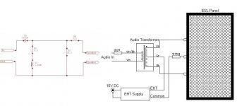
Thanks Calvin I will remeber the mks in the future. What about the attached circuit, is it correct.
circuital correctness
Hi D,
the circuit is corrct so far. Just leave out one of the series resistances (3.3 or 2R2). But keep in mind that just the topologie can be correct for many ESLs (it surely is not Mr. Right for each and every panel) but the component values depend on the ESL´s impedance and surely they must be redesigned for Your panel
jauu
Calvin
Hi all!
Calvin, you've convinced me of using perforated sheets for my first ESL, so I've started looking around for the right sheets.
The place where I used to work has some sheets lying around which I can use for free. They're probably not the best sheets (see the specs below) but I think I could use them for some testing and buy the right sheets later on.
These are the specs:
Thickness: 1.5mm
Hole size: 8mm
Hole distance: 12mm
Hole/material ratio: 40%
Powder-coated RAL9001
Please post your comments on the use of these sheets for a test model!
Kind regards,
Emiel
Calvin,
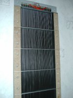
On the 18-10-2005 you added a pix of a curved panel ESL at the bottom of your reply - is this a commercial panel and if so can you provide me with a URL etc?
If you don't want topost this directly in the forum, can you email me privately?
aw (at) vacuum state (dot) see oh m. Of course, close up the spaces and convert the phonetics
Thanks, Allen
Hi,
@Emiel
one of the advantages of perforated metal sheets is the possibility to build panels with small d/s spacings with high efficiency. Efficiency is on the other hand a function of field strength, which is the higher the more ´closed´ the stator is and the more equal the conducting material of the stator is distributed over the diaphragm area. Even though a 8/12mm hole/spacing has a netto openness of ~40% the distribution of conducting areas is too far away. This leads to uneven forces on the diaphragm, hence distortion. There will be high forces exactly below the stator and nearly no force under the midst of the holes. As long as the d/s is higher than the hole diameter this is no problem, but with d/s spacings around 1mm the effect should be kept in mind, because here the hole diameter will always be bigger than the d/s. So use smaller holes and hole distances. 4/6mm is a standard pattern with equal openness as 8/12mm but gives higher efficiency. But there has a minimum hole size to be considered, which depends on the thickness of the sheets! Shortly said: the holes should look like holes not like small tunnels, or anther way: the smaller the holes the thinner the sheet has to be. I use 3/4mm in 1.5mm thickness with app. 1mm d/s. If You plan to use even smaller holes You should consider that an insulative coating on the stator reduces openness (more with small holes than with big holes!). Recalculate openness for the coated case. Coated it should always be more than 25% openness..the more the better.
@Allen
write to You soon ;-)
jauu
Calvin
Very interested in pursuing full range electrostatic design
Calvin,
I'm very impressed with your depth of knowledge of electrostatic speaker design. You raise issues that make me wonder how the old Acoustats worked as well as they did. I still have my old II+IIs and love the sound. Of course they have their deficiencies and maybe that's part of teh reason they're not around any more. Still, the sound is great yet they break most of the rules that you've outlined.
Does anyone make a full range electrostatic now? Are hybrids truly superior to a full range design? I am more of an enthusiast and work in Healthcare IT but previously was a biomed engineer and can handle a tool with the proper motivation. Can you point me in the right direction to learn more?
-steve
Hi,
famous last words!!
"...easy-to-build wired stator"
"...I think I've got it all figured out, there's only one thing need to know:" 🙂 😀 😉 🙂 😎
Just kiddin......don´t be upset. 🙂
Follow the link Ping Calvin - diyAudio
and have a closer look to the frequency response of the raw panel (Multidioc 1. Panel is 125x25cm). You´ll see that above the strong resonance at 180Hz (Fs) the response curve shows a clear dip (250-700Hz). This is due to acoustic phase cancellation and can only be countered electronically (filter) and/or mechanically (much greater width of the speaker by using wider panels or an open baffle)
This is a typical response curve for an open planar speaker and shows the problem of very low crossover points.
Your specs will be hard to achieve. I actually believe You can´t reach them with Your concept at all without throwing a helllot of work into the panels!
Solutions for this panel size:
- higher crossover freq of min. 250Hz
- reduce d/s from 2 to 1.5mm (with >250Hz 1.0mm)
- take a higher transformer ratio 1:100 or more
- use thin wire (best should be Kynar-isolated wire-wrap-wire of AWG24, AWG26 or AWG30)
- even better, though very hard to get in small quantities is corona resistant magnet wire (not the standard types!!) that are intended for inverter use etc. (wires leave You with the not so trivial prob to get between 300 and 800 of them straight and I mean really really very very straight
Solution II same crossover:
- bigger panel with min 400mm width
- 2mm d/s
- higher transformer ratio
- use even more thin wires (600 to 1.600) or
- spare the work and use metal sheets 😉
- use massive electrical equalizing
Solution tip:
- work with metal sheets on Your first project (there are enough probs left that can ruin Your nerves)
- restrict freq-range to >200Hz
- keep things simple and work procedures easy
- listen to those humorless grey-haired old men even if their advices sound a little screwed (guess where they lost humor and gained grey hair? 😀 )
jauu
CAlvin
Calvin,
I'm very impressed with your depth of knowledge of electrostatic speaker design. You raise issues that make me wonder how the old Acoustats worked as well as they did. I still have my old II+IIs and love the sound. Of course they have their deficiencies and maybe that's part of teh reason they're not around any more. Still, the sound is great yet they break most of the rules that you've outlined.
Does anyone make a full range electrostatic now? Are hybrids truly superior to a full range design? I am more of an enthusiast and work in Healthcare IT but previously was a biomed engineer and can handle a tool with the proper motivation. Can you point me in the right direction to learn more?
-steve
Hi,
thanks for the praise. It took me many years to learn and much more hair 🙄 But I´m happy to hear that You can still handle Your tool with proper motivation *hmmh hmmh*

 😀
😀
That my dimensional suggestions are different to those Acoustat used stems simply from the fact that a Fullranger´s demands differ from that of a Hybrid.
If I were faced with the task of building a large FR I doubt that my solution would be much different from Acoustat´s.
I´d surely use a wire stator -probabely rather a system with a few horizontal braces like Audiostatic does instead of the egg crates of Acoustat- and a not too thin wire, for example the PVC insulated H07VU to keep the needed amount of effort reasonable low.
I´d beef up membrane size and keep the d/s below 3mm and would think about a transformer interface that boosts low fequencies like both above mentioned companies use. The stator would be of segmented type, segmentation done using simple resistors. I´d use some stuffing for dampening purposes. As such it would not be an open transparent design like Audiostatic but a closed one like Acoustat, Quad et al.
The reason I don´t build FRs is that I believe that a Hybrid can be superior in almost any field if done properly. The design of my systems allows for a seamless integration of ESL-panel and dynamic bass, which represents the firstmost design problem and main reason of refusal of Hybrids by Fullrange fans. For Fullrange fans this one problem outweighs the deficiencies/disadvantages FRs suffer from.
I always liked ESLs in the midhighs, but was never really confident with their bass- and lowermids performance, the restricted dynamics and often to find difficult drive requirements.
For both schools there are excellent examples for the good as well as in the bad meaning. I´d surely opt for a good FR over a bad Hybrid. But nothing fits my taste as well as a good Hybrid. 😉
jauu
Calvin
thanks for the praise. It took me many years to learn and much more hair 🙄 But I´m happy to hear that You can still handle Your tool with proper motivation *hmmh hmmh*
😀That my dimensional suggestions are different to those Acoustat used stems simply from the fact that a Fullranger´s demands differ from that of a Hybrid.
If I were faced with the task of building a large FR I doubt that my solution would be much different from Acoustat´s.
I´d surely use a wire stator -probabely rather a system with a few horizontal braces like Audiostatic does instead of the egg crates of Acoustat- and a not too thin wire, for example the PVC insulated H07VU to keep the needed amount of effort reasonable low.
I´d beef up membrane size and keep the d/s below 3mm and would think about a transformer interface that boosts low fequencies like both above mentioned companies use. The stator would be of segmented type, segmentation done using simple resistors. I´d use some stuffing for dampening purposes. As such it would not be an open transparent design like Audiostatic but a closed one like Acoustat, Quad et al.
The reason I don´t build FRs is that I believe that a Hybrid can be superior in almost any field if done properly. The design of my systems allows for a seamless integration of ESL-panel and dynamic bass, which represents the firstmost design problem and main reason of refusal of Hybrids by Fullrange fans. For Fullrange fans this one problem outweighs the deficiencies/disadvantages FRs suffer from.
I always liked ESLs in the midhighs, but was never really confident with their bass- and lowermids performance, the restricted dynamics and often to find difficult drive requirements.
For both schools there are excellent examples for the good as well as in the bad meaning. I´d surely opt for a good FR over a bad Hybrid. But nothing fits my taste as well as a good Hybrid. 😉
jauu
Calvin
- Status
- Not open for further replies.
- Home
- Loudspeakers
- Planars & Exotics
- Idea from ESL noob