Greetings and Good Day!
After many years, I have finally got around to finishing my 8-channel amplifier. I will post pictures soon, to aid in troubleshooting.
Components used:
SMPS: MicroAudio Cobra-S2 https://micro-audio.com/store/product/cobra-s2/
^Datasheet: https://micro-audio.com/store/wp-content/uploads/2022/05/COBRA-S1-1.pdf
Amplifier Modules (4): https://shop.icepoweraudio.com/product/300a2/
^Datasheet: https://shop.icepoweraudio.com/wp-content/uploads/2024/04/ICEpower-300A2-Datasheet-1.4_.pdf
The issue is as soon as I turn the SMPS on, it goes into protect mode.
This only occurs when an amplifier module is hooked up. It will sit, powered on with no errors if no amp module is connected. Therefore, I feel the module is sending a DCError signal to the SMPS, sending it into 'protect' mode.
BEFORE I hooked up the SMPS to the amp module, I verified all voltages:

I do not have anything hooked to the 'Basic+ Control Connector', as I am not using BTL. Perhaps I need something from this section hooked up to the SMPS?

I also am not using the 'Aux connectors J4 & J5' on the SMPS. I didn't see anything here I needed. There is a pin for FATAL (error/fail) but so does the J3 connector (and evidently it is working, as it is sending the SMPS into protect).
J4/J5 (not in use):

J3 (HIGHLIGHTED pins in use):

Perhaps I need to hookup J3:5 and J3:6 above? 'Amplifier enable (Opto isolated) E' and 'C'??? I could not find anything on the amp module that made sense to hook them up to.
I really appreciate anybody's help in advance--I'm definitely confused!
Thank you!
After many years, I have finally got around to finishing my 8-channel amplifier. I will post pictures soon, to aid in troubleshooting.
Components used:
SMPS: MicroAudio Cobra-S2 https://micro-audio.com/store/product/cobra-s2/
^Datasheet: https://micro-audio.com/store/wp-content/uploads/2022/05/COBRA-S1-1.pdf
Amplifier Modules (4): https://shop.icepoweraudio.com/product/300a2/
^Datasheet: https://shop.icepoweraudio.com/wp-content/uploads/2024/04/ICEpower-300A2-Datasheet-1.4_.pdf
The issue is as soon as I turn the SMPS on, it goes into protect mode.
This only occurs when an amplifier module is hooked up. It will sit, powered on with no errors if no amp module is connected. Therefore, I feel the module is sending a DCError signal to the SMPS, sending it into 'protect' mode.
BEFORE I hooked up the SMPS to the amp module, I verified all voltages:
I do not have anything hooked to the 'Basic+ Control Connector', as I am not using BTL. Perhaps I need something from this section hooked up to the SMPS?
I also am not using the 'Aux connectors J4 & J5' on the SMPS. I didn't see anything here I needed. There is a pin for FATAL (error/fail) but so does the J3 connector (and evidently it is working, as it is sending the SMPS into protect).
J4/J5 (not in use):
J3 (HIGHLIGHTED pins in use):
Perhaps I need to hookup J3:5 and J3:6 above? 'Amplifier enable (Opto isolated) E' and 'C'??? I could not find anything on the amp module that made sense to hook them up to.
I really appreciate anybody's help in advance--I'm definitely confused!
Thank you!
Try with a single module first. See if that works. Then you'll know it's a case of too much close to zero ohm load, caused by 4 amp modules connected in parallel.
Hi @Extreme_Boky thank you for your help. Unfortunately, I do not believe it is due to the number of modules. I have tried each module individually and it does nothing different than when all four are connected.
Other troubleshooting steps tried:
-Removed ground from wall
-Removed all signal wires (plugs)
-Single module on rubber mat, only aux/power wires
Here are pictures. Maybe they will help!
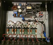
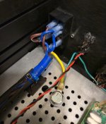
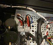
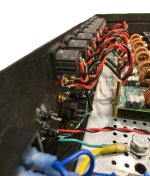
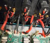
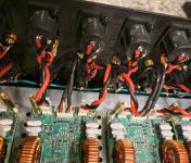
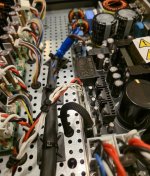
Other troubleshooting steps tried:
-Removed ground from wall
-Removed all signal wires (plugs)
-Single module on rubber mat, only aux/power wires
Here are pictures. Maybe they will help!


Power supply aux connector J4, pin 3, error.
Do you have anything connected to this pin?
Do you have anything connected to this pin?
Been a while since I built a 300A2 amplifier, but here is the table I have in my files for use with the Micro Audio SMPS1K-PFCR2 and SMPS630-G. Only immediate difference I see is I was not using the DC error trigger input.

Michael
Michael
I don't think I used DC error. It would probably be worth reaching out to Sami to better understand how the DC error trigger input is meant to work.
My understanding is that there should be a pull up resistor to pull the output "high" during normal operation as shown in the schematic below from the 300A2 datasheet.

Have you tried measuring the DC error pin on the 300A2?
I agree that trying to use J4 pin 3 might be a good idea, I wonder if it pulls up to a different value than J3 pin 10. The 300A2 datasheet indicates the status output can only be pulled up to 5 V, it might be that the power supply is pulling up to Vaux (+12 V) and this is why you are having issues.

Michael
My understanding is that there should be a pull up resistor to pull the output "high" during normal operation as shown in the schematic below from the 300A2 datasheet.
Have you tried measuring the DC error pin on the 300A2?
I agree that trying to use J4 pin 3 might be a good idea, I wonder if it pulls up to a different value than J3 pin 10. The 300A2 datasheet indicates the status output can only be pulled up to 5 V, it might be that the power supply is pulling up to Vaux (+12 V) and this is why you are having issues.
Michael
Thank you all for the replies. @mdsimon2 you have led me to the exact cause! Excellent analysis!
I did reach out to Sami at MicroAudio. He said the connections all were correct on paper, and to double check that's what I've actually implemented. Since I had already been down that road, twice, I concluded it must be something else.
I measured the DC Error pull up voltage on the Cobra-S2 SMPS, both on J4:3 and J3:10 (might be connected in parallel). What do you know, 13vdc! SO that is well above the maximum allowed by the 300A2 of 5vdc. Bingo.
I severed the DCerror connection and no problems now with the amps/system. I purchased a buck converter to lower the DCerr pullup voltage to something like 4vdc. I hope this doesn't cause issues or introduce any noise--it is a completely self-contained module, not requiring an external power supply, so I'm hoping that keeping it all within the same circuit avoids any problems. IF it needed to be powered by an external source, I would be concerned. I wonder if anybody has used a buck converter for this purpose before? I'll report back!
Thanks again for now!
I am implementing the buck converter right now but I believe I'm overthinking things.
Ground is ground is ground, right? ....right...?
The power/positive side of the buck converter implementation is obvious. No confusion there.
However, the ground/negative side has me a bit perplexed, more than likely for no reason.
Does the ground wire I choose to use matter? For instance, should I use the ground connection that is the pin right next to DCerr on the amplifier module?
Or, if ground is ground, can I use any ground available? If ground is the chassis, can I just connect both the "in" and "out" of the buck converter to the chassis?
I realize I'm overthinking this--LOL
I looked at both user manuals; they were utterly confusing. This is as far as one can go in producing clear and concise technical documentation. Shockingly bad.
I have no idea if what you are saying is input/output to/from the PS or the AMP module. Open drain/source (or open emitter/collector) refers to the output, where the pullup/pulldown resistor is required to allow the current to drive a device connected to that output.
Also, what does this mean?? "I severed the DCerror connection and no problems now with the amps/system." ???
Last edited:
Hi @Extreme_Boky thanks for looking at the manuals--Which part were you confused about? Perhaps I can clear that up!
What I am saying is status output from the AMP module to the PS, where the PS is pulling the AMP's DCerror pin up to 13v currently.
What I am saying is status output from the AMP module to the PS, where the PS is pulling the AMP's DCerror pin up to 13v currently.
What I meant by that is, I physically cut the connection. Excuse my apparent lack of brevity.Also, what does this mean?? "I severed the DCerror connection and no problems now with the amps/system." ???
Unfortunately it appears that the buck converter idea is a non-starter. I can't even get the thing to power on without the PS going into protect state. I suppose it has something to do with the way pull-up resistors work here. I guess the only way to change the voltage is to change the pull-up resistor itself. That sure seems like the right way, rather than splicing something else in there. Oh well, I'm not overly concerned with this extra level of protection. I'll probably email MicroAudio again to see if it is a visible resistor that I could actually change.
- Home
- Amplifiers
- Class D
- ICEpower 300A2 dcerr sent to MicroAudio SMPS immediately