Ian,
Thanks for checking up with us!
So far, tests were good and I’m ready to experiment powering real devices.
My plan is to test with DSC2 DAC today. It requires 5V exactly.
I bought .1% 50K resistors and will now replace the ones I used with the LT3042 while testing.
I’ll share my observations later.

Thanks for checking up with us!
So far, tests were good and I’m ready to experiment powering real devices.
My plan is to test with DSC2 DAC today. It requires 5V exactly.
I bought .1% 50K resistors and will now replace the ones I used with the LT3042 while testing.
I’ll share my observations later.
@iancanada
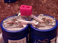
It’s alive!!!
Preliminary results:
1. I pulled the jumper and waited for the voltage to reach 4.8V and then connected the jumper. The PSU was connected to a lowly 5V switcher.
There was quite a nasty buzz in one of the channels, but the music was playing.
2. I pulled the switcher off and the buzz disappeared. The music kept playing only with the Ultracaps.
3. I decided to connect 2x2 LiFePo4 16850 (6.9V) batteries to the Ultracap PSU in order to counter the discharging process.
4. While I was preparing the battery contraption, the music kept playing. By the time I was ready in 30 minutes, the voltage was a bit above 4.5V and the music kept playing.
There’s no way for me to compare the sound, but I can only subjectively say I’m back glued to my chair. I love the concept and measurements of RME ADI-2, but the latter doesn’t glue me to my chair like that.
About my Frankenstein DAC:
BBB->Hermes->Cronus [4x clocks]->DSC2–>Cinemag transformer output stage-> Balanced out.
I’m currently powering the DSC2 registers bypassing the LDO with 5V.
Next step is to power directly the DSC2 logic and Cronus with 3.3V
Last edited:
@iancanada
It’s alive!!!
Preliminary results:
1. I pulled the jumper and waited for the voltage to reach 4.8V and then connected the jumper. The PSU was connected to a lowly 5V switcher.
There was quite a nasty buzz in one of the channels, but the music was playing.
2. I pulled the switcher off and the buzz disappeared. The music kept playing only with the Ultracaps.
3. I decided to connect 2x2 LiFePo4 16850 (6.9V) batteries to the Ultracap PSU in order to counter the discharging process.
4. While I was preparing the battery contraption, the music kept playing. By the time I was ready in 30 minutes, the voltage was a bit above 4.5V and the music kept playing.
There’s no way for me to compare the sound, but I can only subjectively say I’m back glued to my chair. I love the concept and measurements of RME ADI-2, but the latter doesn’t glue me to my chair like that.
About my Frankenstein DAC:
BBB->Hermes->Cronus [4x clocks]->DSC2–>Cinemag transformer output stage-> Balanced out.
I’m currently powering the DSC2 registers bypassing the LDO with 5V.
Next step is to power directly the DSC2 logic and Cronus with 3.3V
View attachment 716924
Thanks for your interesting report.
Is there any way you can compare your Ultracap PS to the LiFePo4 batteries you have as I'm interested in Ian's LiFePo4 battery supply and am wondering if you can hear any difference SQ wise between the Ultracaps and batteries?
Cheers
Thanks for your interesting report.
Is there any way you can compare your Ultracap PS to the LiFePo4 batteries you have as I'm interested in Ian's LiFePo4 battery supply and am wondering if you can hear any difference SQ wise between the Ultracaps and batteries?
Cheers
Well, comparing sound-wise is practically impossible. The reason being the limiting factor, which is the output stage. I'm working with David from Cinemag to identify the best possible solution.
I feel the low end is better extended and more controlled, but don't take my word on that.
I'm interesting with such pure power for my rpi+502dac and have few questions such as:
1. is the isolator compatible with raspberry Pi 3B+ ?
2. is it right way to power rpi from: lifepo4 (linear 5V)+isolator+rpi ?
3. right way to power 502DAC: lifepo4 (battery 6,6V)+UCPi ?
1. is the isolator compatible with raspberry Pi 3B+ ?
2. is it right way to power rpi from: lifepo4 (linear 5V)+isolator+rpi ?
3. right way to power 502DAC: lifepo4 (battery 6,6V)+UCPi ?
Hi luchoh
I appreciate your job with the UCPi. I intend to build UCPi for my DAC (+3.3V/+5.0V). As I see you fed the UCPi to DSC2 DAC and as you reported the DAC played during half hour. I want to ask you what power (or current) consumption have your DAC. Based on your answer I could estimate capacity of UCPi for my DAC.
Thanks.
Hi luchoh
I appreciate your job with the UCPi. I intend to build UCPi for my DAC (+3.3V/+5.0V). As I see you fed the UCPi to DSC2 DAC and as you reported the DAC played during half hour. I want to ask you what power (or current) consumption have your DAC. Based on your answer I could estimate capacity of UCPi for my DAC.
Thanks.
I never measured the DAC consumption. I suspect you can find them in the DSC2 thread.
As an aside, HiddenPilot did a listening comparison between multiple types of powering options and to his ears LiFEPO4 is slightly superior to UCap. I was afraid to test LiFEPO4 direct as the registers have a very close max voltage and didn't want risking frying them.
To my ears LiFEPO4->UCap->DAC vs UCap->DAC is indistinguishable. So I simply power the UCaps with 4 (2x2) LiFEPO4. First though I charge the UCaps from the mains and then I switch to the batteries.
I hope this helps.
Thank you for detailed answer.
I found in the DSC2 thread #66 post of Vit123:
(...)
"Personally I did't measure current consumption. It was done by Pavel and his recommendation is 150-200mA per channel.
As I see in datasheet for 74AHCT595 (shift register used in DSC v2) the Absolute Maximum Ratings is 25mA. We have 8 of them per channel. That's why maximum current is 8x25mA = 200mA"
(...)
I plan use two UCPi (2x2.7V each) charging from 2xLT3042 (3.0V and 5.0V). After charging both LT3042s would be switch of from UCPi. The UCPi would be permanently connected to DAC (during charging too). I want to give up to use LiFePo4. So I interested how long my DAC could play with one charge of UCPi includes 2x325F Ultracaps (BCAP0325 P270 S17 Maxwell/Nesscap).
BTW: Do you know what role make LEDs in UCPi? Could I omit them?
Thank you again.
@JKoch,
The LED's are only indicators. I built mine up without them and they worked just as expected.
I hope this helps!
Greg in Mississippi
P.S. I built my units using NESSCAP Ultracaps. As I reported in post #126 of this thread:
Getting the best out of Allo.com's new Katana DAC...
I heard a slight shelf or emphasis in the upper mids through lower treble using those units. Based on this AND on what I hear using another Ultracap-based supply where I have both units with NESSCAPs and Maxwells, I suspect this is a signature of the NESSCAPS. I am currently building more UCPi's (DIY'd point-to-point as I don't have any more of Ian's boards AND it is nearly impossible to remove the Ultracaps once they are installed due to the massive terminals) using Maxwell Ultracaps to confirm this. I expect to have these running within the next couple of weeks and will report back once I listen to them.
Hi Greg
Thank you for answer. I read all your linked posts. Very interesting. I serious think about Supercaps PSU for DAC. Before your answer I wanted to buy two 325F NESSCAPS in Mouser to make few tests. But as you suggest (sound quality) I will change them to Maxwell's ones. Few days ago I bought assembled LT3042 test board on eBay for tests too.
Thank you again for your support.
An update... First, I WAS able to remove the NESSCAPS from the Ian UCPi boards I have here. It involved using a larger soldering iron (Weller 40 watt pencil) to heat a terminal and using a small, flat-bladed screwdriver to pry the board away from the terminal a bit. This flexed the board a bit at that position, but as long as I went around and did this terminal by terminal, prying up a millimeter or two at a time on each and going around until I had them removed, it did not damage the overall board. The through-hole positions for the NESSCAPS were damaged and likely ruined, but that was not an issue as the Maxwells use different mounting holes.
I popped in the Maxwells and have been running them for about 3 days now. I can confirm that the upper-mid/lower-treble emphasis or shelf is not present in the Maxwells as I expected.
So I am back on track with these with MUCH less work than I expected. I need to test the NESSCAPS. If they still seem ok, at some point I'll make up at least one DIY point-to-point UCPi with a pair and use that for further comparisons. BUT that is not a high priority.
Greg in Mississippi
Update on my DIY Point-to-Point UCPi...
Basically, with all of Ian's boards spoken for, I built several of these this summer and have been using them as a quick way to have more UCPi supplies available for my setups.
I use a common model aircraft/car high-current plug for connections such as these. To make these units fairly durable, I integrated these connectors into the structure and used stout (18g or so) solid copper wire sleeved with Teflon for the connections.
During assembly, I liberally insulate potential short points with Kapton tape to ensure I won't run into problems over time. Once assembled and tested, I insulate ALL metal surfaces (note that the bottoms of these Ultracaps are live!), damped them, then securely wrapped them with large heatshrink. Fully insulating them is a critical step and I don't recommend leaving it out... charged, these Ultracaps will push over 200A into a dead short! You don't want accidents with these!!!
Connections are Vin, Vout, charging regulator, and voltage monitor. I used these voltage monitors when initially charging them and putting them in a setup, but remove them after things are setup and stable:
bayite 3 Wire 0.36" DC 0~30V Digital Voltmeter Gauge Tester Blue LED Display Panel Mount Car Motorcycle Battery Monitor Volt Voltage Meter with Reverse Polarity Protection Pack of 5: Amazon.com: Industrial & Scientific
I left out the on-off header from Ian's orignal configuration. I first pre-charge them to the target voltage, then plug them in to use and disconnect them when not in use. I also didn't include the charging filter choke as I have been using these with quiet power supplies constantly connected to float-charge the Ultracap pair. When first charging them to the needed target voltage (typically 3.3V or 5V) I use Ian's LT3045 regulators with a 250mA current limit to control the charging rate. Once charged, if I used a supply with the same voltage as the target voltage, I replace the regulator with a small jumper.
A good example of where I used a charging supply of the same voltage as the target voltage is for powering an RPi or RPi substitute. I used a 250mA current limited 5V Ian LT3042 regulator fed from one of the typical 5V supplies I would use to power the RPi to charge the DIY UCPi to nearly 5V (they won't get all the way there due to the LT3042 dropout voltage). Then once the DIY UCPi is charged and before I connect it to the RPi, I remove the current-limited regulator and jumper input to output so that it is fed directly from the 5V supply. I do this because even though the supplies I use for this application are current-limited, because they need to have a current-limit of greater than 1A (I generally use 3A-3.5A supplies for my RPis), they'd get VERY hot during the charge phase, likely more than the heatsink will handle. BUT once charged, I need a current limit higher than the 250mA of Ian's LT3042 regulator boards to keep the Ultracaps charged when powering an RPi (with no charging supply, the USPi powering an RPi runs down to about 4V in about 10 minutes... not very useful!)
I leave it to the readers to duplicate this for their own setups and connector requirements.
Finally, here are my dire warnings for use of supplies with Ultracaps...
DON'T EVEN THINK OF trying this at home, ESPECIALLY IF WHEN YOU LOOK AT IT, you have to ask a LOT of questions about how to implement it and do it safely.
Please understand the amount of energy stored in each of the Ultracap pairs is STAGGERING! Back in the 1978, I built my first full audio kit, a Hafler DH-200 amplifier. This 100wt/8ohms rated amplifer had a +-60V supply, with 10,000uF/80V capacitors as stock. That calculates out to 18 Joules of energy stored in each cap. A UCPi supply with 2 325F/2.7V Ultracaps and each charged to 2.5V comes out to 1015 Joules or 56x the energy stored in each Hafler amplifier cap!!!!! AND these caps will release that energy in metal-welding hundreds-of-amps rates. That won't do anything good for your DAC (or anything else connected) if you accidently short something!
Also someone who works with these told me they will kill. I didn't think so before because of the low-voltages involved, but that is too danged serious of a warning to ignore!
Also, this setup has NO safeties built-in. I also use a number of Uptone Audio LPS-1.2's to power various pieces of gear in various configurations in my systems. These 'off-the-grid' devices use 2 continually-swapped banks of 7 10F Ultracaps to provide the output voltages (Let's estimate about 220 Joules per bank when used at the max output voltage). The designer, John Swenson, spent a LOT of effort designing, coding, and testing the processes to keep the units ALWAYS safe, including:
- power-on Ultracap discharge cycle
- controlled charge rates with no output until both banks are charged
- active charge level balancing
- Overtemp and overcurrent cutoffs
- power-off Ultracap discharge cycle
These raw Ultracp setups HAVE NONE OF THESE! ONE USES AT YOUR OWN RISK!
You can find info on these Ultracap setups here:
Post #1 of this thread, with some useful links and references.
https://www.diyaudio.com/forums/pc-...dac-hats-raspberry-pi.html?highlight=ultracap (There are comments by Ian and a few others throughout this thread)
Develop ultra capacitor power supply and LiFePO4 battery power supply
Again, if you read all of the relevant comments referenced above and the schematic (see post #1 of this thread for a pointer) AND you have to start asking questions, please don't pursue this route. Just wait for Ian's ready to use-version that hopefully will have less of a possibility of severely damaging your equipment or you.
Greg in Mississippi
P.S. For float-charging supplies, with DACs or DAC support circuits (isolators, reclockers, etc) I use 1 Uptone Audio LPS-1.2 per UCPi set to the next higher voltage above the target voltage and leave the Ian LT3042 charging regulator in place. With RPis or substitutes like the excellent Allo USBBridge Signature, I use either the 3.5A output of an Allo Shanti or a modified 12 watt (5V/2A) K&K Audio Low Voltage supply with the charging LT3042 regulator jumpered out after the UCPi gets to the 5V target voltage. Note in some setups I prefer the Shanti, in others the K&K. (AND before one points out the cost difference, once you factor in the cost of the K&K supply mod parts (larger value raw DC and output Cs, higher current Schottky diodes, polyprop bypass caps) and that the Shanti includes 2 supplies and a case, I consider them about the same cost/value).
These are currently my best sounding supply setups for both the 5V inputs on an Allo Katana, the 3.3V inputs on an Ian GB FiFoPi/DAC setup, and for an RPi or an Allo USBBridge Signature.
Attachments


I followed the idea of Greg for the ultracaps. As a diy drone builder I had some connectors lying around 😉
The ultracaps are used on the ps for the fifopi and andrea mori clock (3.3v supply).
It’s now running in. I am very curious of the results.
The caps are connected in parallel to the batteries. I would like to use them as a r-c filter on the battery supply but this is not easy to do. I expect using a filter point with the resistor will result in even less noise from the battery.
It could be done by just connecting them on the output of the battery supply but in that way the capacitors will drain when power is off (it is behind the relais) and will need filling at power up, and as filling them with a 3,9ohm resistor takes about one hour this is not usable.
Has anyone found a solution for this by modifying the battery output line to the relais and inserting the r-c filter in this way?
Regards,
Attachments
Last edited:
I dont see any 'balance boards' on these diy point to point set ups. The info I have gained from some YouTube videos shows these little boards mounted to the tops of the caps. Once the voltage limit is reached an LED lights and it discharges to hold the set voltage. Sounds like a nice solution. They seem to come configured for 2.5v. They allow a single feed of the charging/target voltage to be applied safely without over charging, although it was noted that if charging at CC of too many amps would allow a small over voltage. This is not something I wish to gamble with.!
I has considered using a Salas L adapter along with an LDO to charge....switching out the ldo once charged.
I would also use those small LED voltage indicators.
What are you guys doing for balancing? I see mention of 'balancing resistors' but how do these do the job correctly and safely?
This is the sort of thing I refer to
2.7V 500F super capacitor 3.5cm Balancing Protection Board GL | eBay
For my DIY UC pair PTP builds, I used Ian Canada's UCPi schematic as a basis, but only kept the Vin, Vout, UCs, balancing resistors, and 3-pin connector for the current-limited regulator. AND I added a connector to measure voltage with the small voltage monitors I linked in some of my previous posts on these.
Ian's UCPi schematic is linked in post #1 of this thread.
On my original builds I used the 1K balancing resistors in Ian's original schematic. Later Randytsuch shared a rationale and formula to calculate those resistors... I think he posted it on a thread at TirNaHiFi.org at one point, but I didn't take the time to find it there. From the email he sent:
"was looking yesterday to figure out the value of the balancing resistor, and found this info:
Passive Balancing: One technique to compensate for variations in parallel resistance is to place a same valued bypass resistor in parallel with each cell, sized to dominate the total cell leakage current. This effectively reduces the variation of equivalent parallel resistance between the cells which is responsible for the leakage current. For example, if the cells have an average leakage current of 10uA +/- 3uA, a 1% resistor which will bypass 100uA may be a good choice. By using this resistor in parallel to each cell the average leakage current is now 110uA +/- 4uA. Introduction of this resistor has now decreased the variation in leakage current from 30% to 3.6%.
Leakage is .75ma for the BCAP0360 P270 S18
So if you aim for 10x that its 7.5ma or 0.0075 a with balancing resistors
For a 3.3V power supply, each cap sees 3.3/2 = 1.65V
v=ir r =v/i = 1.65/.0075 = 220 ohm
I will probably go even smaller, around 75 ohms would consume 22ma. A smaller value resistor will use more current, but will do a better job balancing the voltage."
I noticed Ian is using 470R or so resistors in his scheme for paralleling 2 325F-350F UCs instead of the 1K in the UCPi. On my next set of PTP UC pair builds, I used 499Rs across each UC for balancing. Then when I built up a couple pair of 3000F UC pairs, using the formula above gave me something around 100R. I used 100Rs.
The balancing Rs are not an exact science... a close value will work ok. AND even the 1K Ian used in his original UCPi should do a fair job of keeping the 2 UCs in balance, just not as good as the recommended lower value.
I say all of this because from an 'Everything Matters' perspective, I like the simplicity of passive balancing Rs and a current-limited/temperature-limited regulator for charging. AND I am cautious about the impact the boards on the UCs you mention will have on SQ.
In post 954-956 and 958 of the "IanCanada's Latest RPi GB Goodies..." thread, randytsuch describes how he handled charging and heat using Ian's GB LT3042 regs. I have used both those and some ADM7150-based regs (earlier design from Acko) to charge mine. Of course the ADM7150 with an 800mA current limit charge them faster. BUT unlike Randy, I haven't put heatsinks on my charging regulators, so I generally use the LT3042 units and will only put in the ADM7150 units when I am either in a hurry or at the end of a charge to get them that last 1V or so fairly quickly. Also I assembled Ian's regulators with a 0R in the current-limit-setting resistor position so they use the chip's default 200mA-250mA current limit.
Using either of these regulators without heatsinks has been un-eventful for me, with no thermal shutdowns or other 'events'.
AND I am cautious about using an L-Adapter directly to charge large (>5F or so) UCs as just in a quick check of the circuit I don't see any current-limiting or temperature-limiting. Those UCs are a near-dead short until near the terminal charging voltage and will take every amp of current your supply will muster. Even a tenth of a volt potential difference can cause a significant current flow... I paralleled a 350F UC pair at 5.0V with a 3000F UC pair at 5.1V and got a spark when I connected them.
OTOH, if the circuit on the UC pairs you list perform current limiting, the L-Adapters should be ok.
Bottom line, without having the schematic for the added circuitry and a detailed description of the functionality, I can't say whether those cap pairs are both a good idea and a safe one. OTOH, even though it is a bit of a pain, passively-balanced UC pairs with appropriately-sized resistors charged through a current-limited/temperature-limited regulator works stunningly and has been safe as long as protocol is followed.
BUT YMMV, of course!
Greg in Mississippi
P.S. Update... Jimk04, I missed you were planning to use small LDO's in the charging circuit, so I assume your LDO choice will handle the charging current limiting. Sorry I missed that before I wrote everything above!
As for changing out the LDOs, I run 2 types of configurations... some with the charging supply at a higher voltage than the target voltage... say a 5V supply for 3.3V at the UCs. With this setup I leave the LDO in place. AND I have found the LDO quality matters when I do that. I have swapped between the LT3042 boards, the ADM7150 boards, and LDOVR.com's LT3045 boards. I prefer the latter sonically in this configuration.
In the other configuration, the charging raw DC supply is the same voltage as the target voltage... for example a Shanti or a modified K&K Low Voltage supply at 5V to feed UCs at 5V for powering my USBBridge Signatures. While I know the regulators in the K&K have current/temperature-limiting (LT3083s) and suspect the scheme used in the Shanti has good current/temperature-limiting, I don't want to stress them. SO I charge them up with the LDO in place until the voltage stops climbing... for a 5V input it typically stops in the 4.8V range. Then I remove the charging LDO and replace it with a wire shunt from input to output. Yup, the UC pair will draw ALL the current the raw supply can source for a few seconds, but never long enough to damage them (so far... knock on wood!). Even with the 3000F UC pairs.
BTW, Ian's UcConditioner in development will make the whole process very simple for 5V output voltages AND do so with very little chance of sonic impact. Last I heard from Ian, he will have charge-current limiting built into the final units. AND is looking at very low on-resistance MOSFETs instead of relays for the connection of the UCs to the load.
Last edited:
I have found that the purple ebay lt3042 3v3 regs wont charge my UC pair from empty. The led remains unlit and the thing got hot fast. Seems to have survived I guess it went into current limiting shutdown.
So I charged them with my bench psu. Set to 3v3 CV it peaked at the psus max of 5.3A and dropped into CC mode until the voltage rose a bit and then the current dropped and it went back into CV and charged to the 3v3 target.
It didnt seem to take long..a few minutes. I thought I was going to be there some time.
Plugged it into a Fifo I have sat here and it remained lit for a good hour and was still lit when I unplugged it....voltage in the caps dropped to 2.6v.
Shall try the lt3042 again now the caps have some charge left in them.
@jimk04;
Do you have my free LT3042 PCB? My LDO board doesn't have problem with charging UCs. I set the current limitation to 200mA, it takes around half hours or more to charge a 350F UC and doesn't go that hot.
Good weekend.
Ian
Do you have my free LT3042 PCB? My LDO board doesn't have problem with charging UCs. I set the current limitation to 200mA, it takes around half hours or more to charge a 350F UC and doesn't go that hot.
Good weekend.
Ian
- Home
- Amplifiers
- Power Supplies
- Ian's Ultracapacitor Explore PLUS - build thread