Hi there.
Is it possible to make af coaxial spdif output on a Marantz MR 2021 (MR2020) ?
There is a dac chip (TDA1311AT) on the board and it seems like it receives a I2S signal ?
Can i use some I2S to coaxial board and connect it to the serial interface and get a digital output to my dac ? (TDA1311AT disconnected)
Or is there another way you think is better or easier
I have tried to use the analog line out to line in on my pre amp, but its way to high level, and making distortion, and i would really like to make a digital output on this Marantz MR 2021
If i can make an digital output with an I2S to coaxial spdif board and you have ideas to a (cheep) board, please let me know 😉
I have to say that iam not a electronic nerd at all 😀
The service manual to the Marantz MR 2021 is here and i picture of the TDA 1311AT connection
Marantz MR2020 Service Manual (Page 33 of 42)
Page 33
________________________________________________________

It is fairly simple to convert from I2S to SPDIF. I have made some designs in the past using CS8406 and AK4118A for that purpose (only one of the IC's in a design).
There might be a challenge here, since there may not be a suitable MCLK available, which these IC's require. My latest design uses a PLL to generate that from the SCLK, so no ned for a separate MCLK. If an MCLK is available, it will simplify the design.
I don't know if off the shelf PCB's with the desired functionality are available.
It is fairly simple to convert from I2S to SPDIF. I have made some designs in the past using CS8406 and AK4118A for that purpose (only one of the IC's in a design).
There might be a challenge here, since there may not be a suitable MCLK available, which these IC's require. My latest design uses a PLL to generate that from the SCLK, so no ned for a separate MCLK. If an MCLK is available, it will simplify the design.
I don't know if off the shelf PCB's with the desired functionality are available.
PM sent 😉
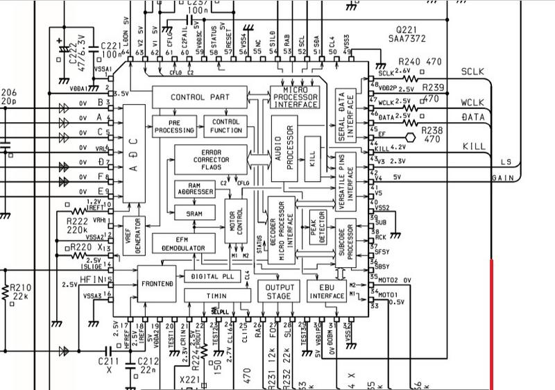
Alas, the OP has cut off the most relevant part of the schematic posted, the SPDIF output.
You can see it all here = Marantz MR2020 Service Manual (Page 33 of 42)
If you take a look at the chip SAA7372 you will find the SPDIF output already available at pin 31. It is the EBU output. Goes to connector J205 D-OUT. Pin 31 is marked DOBM. It is a short for Digital Out Biphase Mark (that´s SPDIF).
If you take a look at the chip SAA7372 you will find the SPDIF output already available at pin 31. It is the EBU output. Goes to connector J205 D-OUT. Pin 31 is marked DOBM. It is a short for Digital Out Biphase Mark (that´s SPDIF).
Thank you very much 😉
Can i use this output directly in my dac
Seems like there is an optical output if you take a look at page 17 and the board PX54. At the bottom there it seems like there is a TOSLINK transmitter. If that is the case a converter from TOSLINK to SPDIF would be the easiest road. If not you have to solder this one together. TTL level SPDIF taken from J205 and connect output of circuit directly to a female RCA connector for your coax to DAC.
Taken from this site: S/PDIF Digital to Analogue Converter
Taken from this site: S/PDIF Digital to Analogue Converter
Attachments
Last edited:
Seems like there is an optical output if you take a look at page 17 and the board PX54. At the bottom there it seems like there is a TOSLINK transmitter. If that is the case a converter from TOSLINK to SPDIF would be the easiest road. If not you have to solder this one together. TTL level SPDIF taken from J205 and connect output of circuit directly to a female RCA connector for your coax to DAC.
Taken from this site: S/PDIF Digital to Analogue Converter
Perfect, and thank you alot 😉😉😉
Seems like there is an optical output if you take a look at page 17 and the board PX54. At the bottom there it seems like there is a TOSLINK transmitter. If that is the case a converter from TOSLINK to SPDIF would be the easiest road. If not you have to solder this one together. TTL level SPDIF taken from J205 and connect output of circuit directly to a female RCA connector for your coax to DAC.
Taken from this site: S/PDIF Digital to Analogue Converter
Hi again.
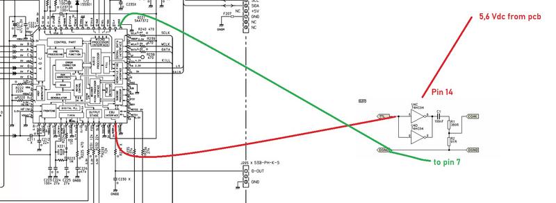
I have connected the 74CH04 to the DOBM, but its not working.
Do i have to have "something" between the DOBM and the 74CH04 ?
The 74CH04 are connected like at the picture and getting 5,6 Vdc
No sound, no output 😕
Do i need a pulsetrafo ?
Last edited:
No, you should be able to get the signal you want for the input to the 74ch04. Have you connected the ground (earth) as well? Connect the input directly to pin 31 on SAA7372.
This output is 5 volt TTL pulses. In the schematic R234 is marked with an X. May be this resistor is not mounted on the card. Use this point for a direct connect.
This output is 5 volt TTL pulses. In the schematic R234 is marked with an X. May be this resistor is not mounted on the card. Use this point for a direct connect.
Last edited:
I have connected it directly to pin 31.
The R234 are not mounted on the pcb and the value isn´t in the schematic
Ground (pin 7) and signal gnd are mounted to gnd on the pcb (pin 49 on the SAA7372)
The R234 are not mounted on the pcb and the value isn´t in the schematic
Ground (pin 7) and signal gnd are mounted to gnd on the pcb (pin 49 on the SAA7372)
If you measure 0 volt or 5 volt on pin 31 you have no signal. Should be the average of the pulse train , around 2 volt to 3 volt.
- Home
- Source & Line
- Digital Source
- I2S to SPDIF