Do you have the datasheet for the EP7212?. If not the datasheet for the EP7212 states that the format for the DAI (Digital Audio Interface) is a subset of the I2S format. It is fixed at 44K1 and has bitclock of 128Fs yielding 128 bit clock cycles per L/R frame. Data is MSB or Left justified without the one cycle delay associated with I2S. There would appear to be a conflict between the text and the diagram as regards LRCLK. The diagram shows LRCLK=H as signifying L channel data but the text states otherwise.
ray.
ray.
I haven't been able to locate the EP7212 datasheet until just now. I will have to read through it. So it sounds like maybe the two (EP7212 and CS8420) are incompatible? I have tried all the formats the CS8420 and CS8405 support and none of them work right.
I'll still try some resistors, but I don't think they will help.
Thanks,
Stu
I'll still try some resistors, but I don't think they will help.
Thanks,
Stu
Sorry for posting a probably very trivial question.
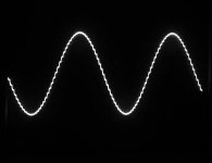
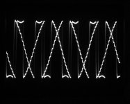
I made my first I2S-DAC board today. With TDA1543/NE5532 to start in the simple. I use a PCM2706 USB-to-I2S board. It sounds surprisingly well considering that the TDA1543 is about the cheapest audio DAC around (photo 1). But, when I increase the signal level on the PC (with Linux), the sound suddenly becomes heavily distorted very suddenly (photo2).
The scope-photos are takes with a 1KHz/0dB input signal. At a certain moment it seems like there is a register overflow, probably in the PC. Am I right in this assumption and is there something I can do under Linux to improve the situation?
At present I “calibrate” the PC volume using the 1KHz/0dB .wav file adjusting the volume at a level just below where the distortion appears. For the rest I use the volume control on the analog side.
Attachments
PCM2706 is without volume control function, perhaps linux drivers ... if you don't have a similar problem on windows, there will be something with linux drivers
Thanks for your reply. I have the same problem under Windows 10.
I rebuild the board to use a TDA1387 instead of the TDA1543 and with this similar I2S interface I had no problems. Though the TDA1387 was ridiculously cheap and I only used one (no parallel configuration), it sounded surprisingly good with .flac files.
I believe you are right, it should be in the driver or a mismatch of the PCM2706 with the TDA1541. It looks like the word is shifted one time too much towards the MSB (overflow) instead of being limited to FFFF as for ordinary clipping.
I appreciate that you took time to comment.
Could be a likely reason. I also tried with my CM6631a USB->I2S board. Same problem.
For the TDA1543, the datasheet states:"The most significant bit (bit 1) must always be first" and talks about I2S input "format"`. What that exactly means in relation to "left justified" and normal I2S format I do not know at present. I have to study the alternative input formats.
It is not that I insist on using the TDA1543, in particular now that my TDA1387 seems to perform better in almost all ways.
I assumed for a start that it was a trivial issue among the experts but the TDA1543 may be long time forgotten.
Many thanks for your suggestion.
Last edited:
Have a look at figure 62 of https://www.ti.com/lit/ds/symlink/s...=https%3A%2F%2Fwww.ti.com%2Fproduct%2FSRC4392 for an overview of I2S, left justified and right justified. Putting a left justified signal according to the picture on an input that expects I2S would result in a one-bit shift and overflows when you exceed half scale, as well as a swap of left and right. As it's a Sony document, the signal lines have the Sony rather than the original Philips names.
One thing I don't get, though: the TDA1387 and TDA1543 are both from Philips/NXP and I2S was invented by Philips, so you would expect both of them to be made for I2S. Both should then have the same problem if the input signal is left justified according to figure 62.
One thing I don't get, though: the TDA1387 and TDA1543 are both from Philips/NXP and I2S was invented by Philips, so you would expect both of them to be made for I2S. Both should then have the same problem if the input signal is left justified according to figure 62.
Try to slow down Data with 1k resistor, if not helped install the resistor on BCK (either one or the other). Use wires shorter than 10cm.
Many thanks, Marcel. It must be central for the explanation.
Yes, while the DAC constructions of the TDA1543 and TDA1387 are different, you would expect the three-pin I2S interface designed by Philips to function alike.
Actually, my use of TDA1543 and TDA1387 is start of a "confined Christmas" -project including other I2S DACs like ES9023, PCM5102, CM4398, PCM1794, ES9018Q2M and AK4490 (the cheap stuff). I will then see how many of those chips that do not behave as expected and I will give the chips a chance to perform with a correctly designed buffer/filter and decent power regulators. Most of what I see on cheap DAC boards from the east fail on the analog side and for the power supply. It's a pity to use a high performance DAC chip and fall on analog and supply design.
A merry Christmas to you. The new year should (hopefully) be better than the past.
@miro1360. Thanks for the suggestion, I will try one of the Christmas days. A merry Christmas to you.
One thing I don't get, though: the TDA1387 and TDA1543 are both from Philips/NXP and I2S was invented by Philips, so you would expect both of them to be made for I2S.
The TDA1387 and TDA1543 are both I2S input but, ultimately, NXP/Philips are in the business of selling chips so the TDA1543A and TDA1545 support the Japanese formats.
What helped on my PCM1794:
Active and Release the /reset After all Supply voltages are Good.
With this you get the right confuguration in HW mode, since the Pins get the proper voltage when sensing after start up.
Maybe it‘s a little thing which causes wrong Format configuration.
Additionally you could make a Input signal, That contains only DC. With a DC SIGNAL the SDATA Word will Stay steady on the scope. No eye diagram
- Home
- Source & Line
- Digital Source
- I2S Problems