Yes. That is why the JLSounds use 45/49Mhz clocks.
I supposed, thanks.
I have considered the transformer solution too, but wouldnt that result in a phasshift/time delay between the MCLK and the other i2s signals? or does that not matter for an application like this?
A phase shift between MCLK and the I2S signals doesn't matter.
A transformer for MCK? Never heard of this idea. What would happen to the square wave? Would it not be worse than jitter?
If a suitable wideband trnsformer is used, the jitter can be very low. Much lower than with digital isolators.
I would not anticipate jitter but rather a waveform with sloping edges. No idea what effect this would have. Can you suggest specs for a transformer or even a specific part?
It is used in Frex's OSVA, see OSVA - Open source Versatile Analyzer
It was suggested here: SAR ADC for high performance audio ADC project [LTC2380-24]
Frex had already considered it, see a couple of posts later.
Some measurement results can be found here: SAR ADC for high performance audio ADC project [LTC2380-24]
The Würth 749010310 (LAN) seems to work very well. I am sure there are a lot of other possibilities.
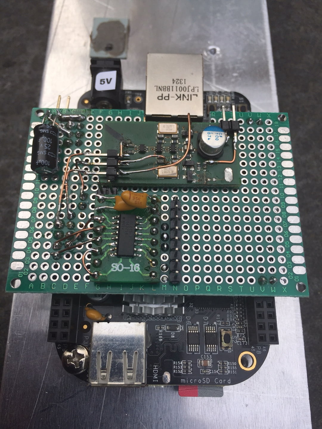
I did an isolator chip in my I2S signal with an IL715 chip.
It is a 4-channel supporting 100 MHz so 45/49 should pass through o.k.
I use it for I2S only so never tested it at higher than 12 MHz BCK so you have to test yourself how signal quality will be through the chip.
I use a Beaglebone Black with add-on board for dual clock 22/24 MHz and the IL715.
My measurements show a nice cleanup of PC noise once passed the isolator.
Hardware:
44.1 LRCLK before isolator:
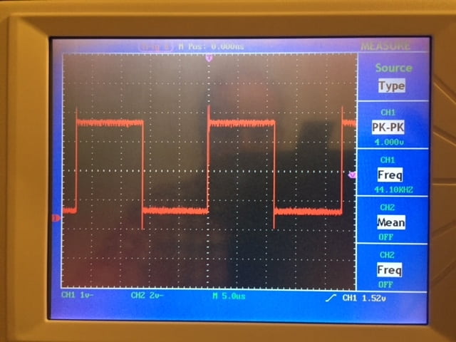
After the isolator:
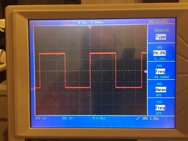
44.1 BCK before isolator:
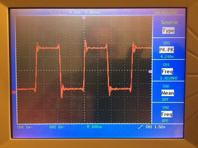
After:
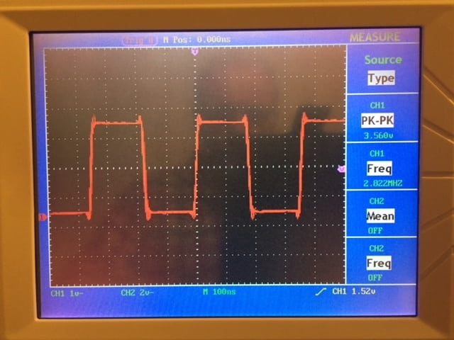
The power supply used for both sides of the chip are AMS1117 regulators for 3.3V out.
It is a 4-channel supporting 100 MHz so 45/49 should pass through o.k.
I use it for I2S only so never tested it at higher than 12 MHz BCK so you have to test yourself how signal quality will be through the chip.
I use a Beaglebone Black with add-on board for dual clock 22/24 MHz and the IL715.
My measurements show a nice cleanup of PC noise once passed the isolator.
Hardware:
44.1 LRCLK before isolator:
After the isolator:
44.1 BCK before isolator:
After:
The power supply used for both sides of the chip are AMS1117 regulators for 3.3V out.
Sorry to resurrect this thread, but I'm wondering what exactly is necessary to use the ethernet-style transfermers to filter the signals. It looks like it is as straightforward as installing the transformers inline, but that seems too simple to me.
I am trying to clean up an i2s signal from a particularly noisy wifi/bluetooth/usb streaming board (Arylic) that has some ugly switching noise overlayed on everything.
I am trying to clean up an i2s signal from a particularly noisy wifi/bluetooth/usb streaming board (Arylic) that has some ugly switching noise overlayed on everything.
Results look great above! It has 100ps jitter.
LAN xformer needs DC free signal, so cannot be used for data.
LAN xformer needs DC free signal, so cannot be used for data.
- Home
- Source & Line
- Digital Source
- I2S isolation for DAC